34410A/11A/L4411A Service Guide 111
Disassembly and Repair 4
34410A/11A Mechanical Disassembly
For procedures in this manual, the following tools are required for
disassembly:
• T20 Torx driver (most disassembly)
• T15 Torx driver (fan removal)
• Flat Blade screw driver
The following tools may also be needed if further disassembly is required.
• 9/32” nut driver (rear–panel GPIB connector)
General Disassembly
1 Turn off the power. Remove all cables from the instrument.
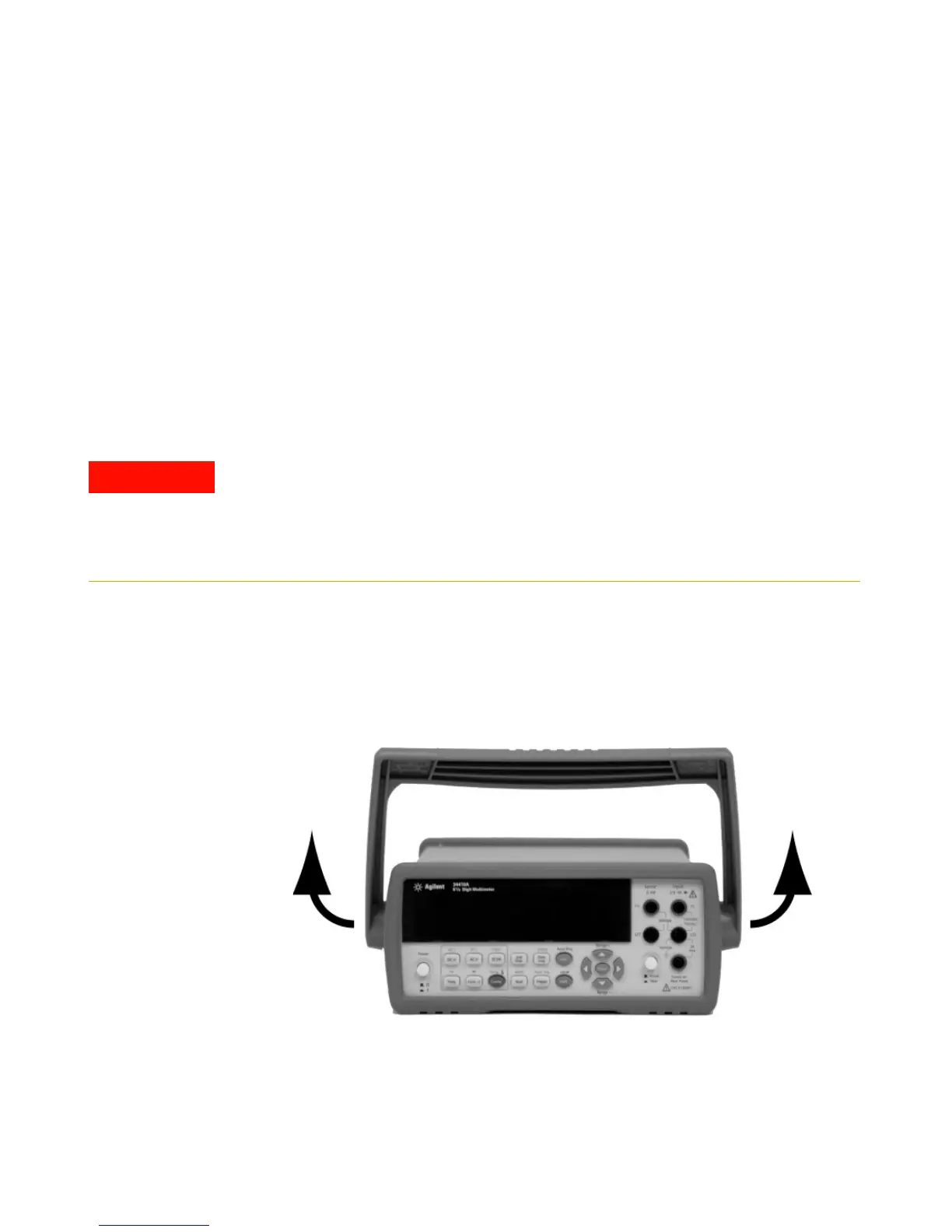
2 Remove the Carry Handle. Rotate the handle upright and pull out from
the sides of the instrument.
SHOCK HAZARD. Only service–trained personnel who are aware of the hazards
involved should remove the instrument covers. To avoid electrical shock and
personal injury, make sure to disconnect the power cord from the instrument before
removing the covers. Some circuits are active and have power applied even when
the power switch is turned off.

 Loading...


