34410A/11A/L4411A Service Guide 117
Disassembly and Repair 4
L4411A Mechanical Disassembly
For procedures in this manual, the following tools are required for
disassembly:
• T10 Torx driver (most disassembly)
• T20 Torx driver (power supply removal)
• Flat Blade screw driver
The following tools may also be needed if further disassembly is required.
• 9/32” nut driver (rear–panel GPIB connector)
General Disassembly
1 Turn off the power. Remove all cables from the instrument.
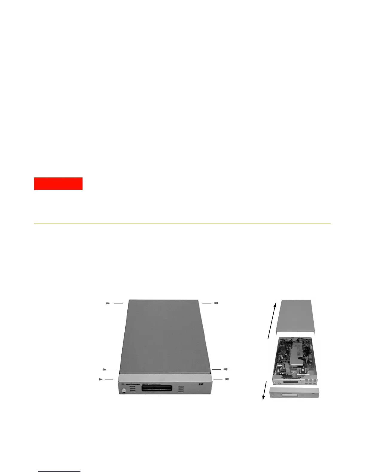
2 Remove the top cover and font bezel. Remove the four Torx drive
screws, two on each side of the cover and slide the cover back and off
the instrument. Remove the two Torx drive screws from the front bezel
and slide the bezel off the instument.
SHOCK HAZARD. Only service–trained personnel who are aware of the hazards
involved should remove the instrument covers. To avoid electrical shock and
personal injury, make sure to disconnect the power cord from the instrument before
removing the covers. Some circuits are active and have power applied even when
the power switch is turned off.

 Loading...


