130 Agilent Restricted Agilent 5110/5100 ICP-OES Service Manual
4 Removal/ Installation, Replacement and Adjustment
Polychromator
6 Replace mirror assembly and tighten 3 screws.
7 Return the instrument to normal operating conditions by replacing components in reverse
order.
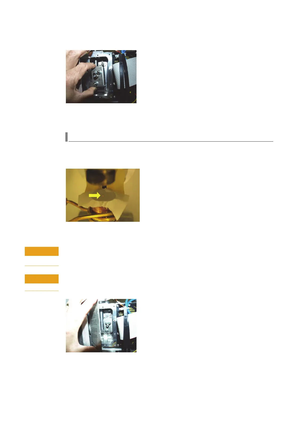
Entrance slit
The entrance slit is recommended to be replaced with the alignment slit when performing a
pre-optics alignment however alignment can be completed with instrument slit in place but with
a smaller laser image available. (See below).
Care should be taken to ensure the instrument slit assembly is returned before replacing
polychromator covers.
The entrance slit is located between the polychromator casting and pilot mirror M5. Care
must be exercised when removing the slit assembly to ensure that the slit assembly does not
strike the pilot mirror.
Do not unplug the camera board while power is applied. Failure to follow this instruction will
result in damage to the camera board.

 Loading...


