86 Agilent Restricted Agilent 5110/5100 ICP-OES Service Manual
4 Removal/ Installation, Replacement and Adjustment
Instrument Control module
Instrument Control module
1 To replace any of the Printed Circuit boards from the Instrument control module follow the
below hierachy.
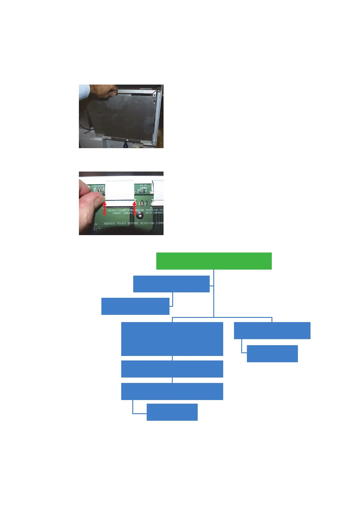
2 To disconnect ribbon cables push up tabs on either side of the connector to release ribbon.
Loosen 2 torx screws and remove outer
cover of control module.
Remove 2 torx screws from
P500 board
Remove P500 board
Remove 9 torx screws from
Instrument Control board. Remove 4
accessory connector standoffs (5BA)
and disconnect wiring harness
Remove Instrument Control board
Remove 6 torx screws from Camera
Control board
Remove Camera
Control board
Remove 2 torx screws from
Camera Board
Remove Camera
Board

 Loading...


