B Cabling Diagrams and Remote Start/Stop
74 Installation and First Startup
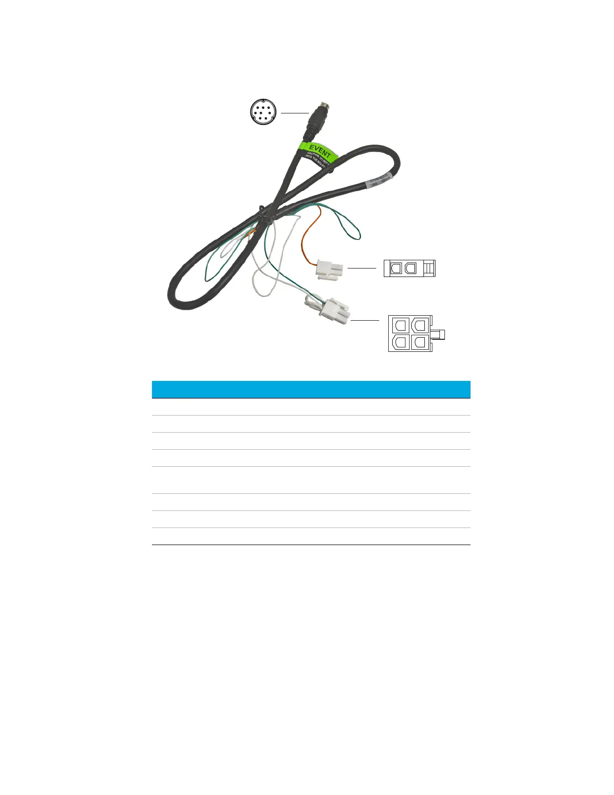
Connector 1 pin Wire color Connector and pin Function
1 Yellow
2Black
3Red
4 White Connector 3 pin 1
*
* Connector 3: Pin 1 is jumpered to pin 2. Pin 2 is jumpered to pin 4.
Ground
5 Orange Connector 2 pin 1 Contact closure 1, 48 V
AC/DC, 250 mA
6 Green Connector 3 pin 3 Contact closure 1
7Brown
8Blue
2
8
1
6
1
2
3
4
12
Connector 1
Connector 2
Connector 3

 Loading...


