194
Chapter 7 Plug-in Modules
N2264A Multifunction Module
7
N2264A Wiring Information
There are four methods available to connect to the N2264A:
•
A screw terminal block, the N2294A (described on page 277).
•
A direct wiring (insulation displacement) connector, the N2296A
(described on page 278).
•
A DIN96 to twin D50 Cable, the N2297A (described on page 279).
•
A DIN96 to four D25 Cable, the N2299A (described on page 281).
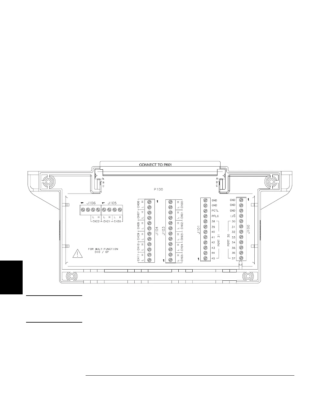
The screw terminal block (N2294A) is shown below. To use the other
connection options, you will need to use the pinout information given on
page 195.
Caution 12 pins (6 H and 6 L) are provided for each channel of the 3-Channel
High-current GP Relay. Make sure to use ALL 12 pins whenever the
switched current exceeds 1 amp.
CONNECT TO P601
 Loading...