1-15
Troubleshooting
Troubleshooting Assembly–Level Problems
Symptom: Hardkeys or softkeys do not work
The A1 Keyboard contains the hardkeys and softkeys switches. The keys are arranged in a matrix
(shown below) with the control lines KEYCOLx and KEYROWx on the x and y axis. When you press
a hardkey or softkey, one cell of the matrix is activated; the normally TTL low KEYROWx of the
active cell pulses high, and the normally TTL high KEYCOLx of the active cell pulses low.
1. Ensure that the front panel green power on LED is on. If it is not on, refer to “Power Supply
Troubleshooting” on page 1-17.
2. To ensure the signal generator is not being controlled remotely, press the
Local hardkey.
3. Use an oscilloscope to monitor the KEYCOLx and KEYROWx pins of the key that is not working
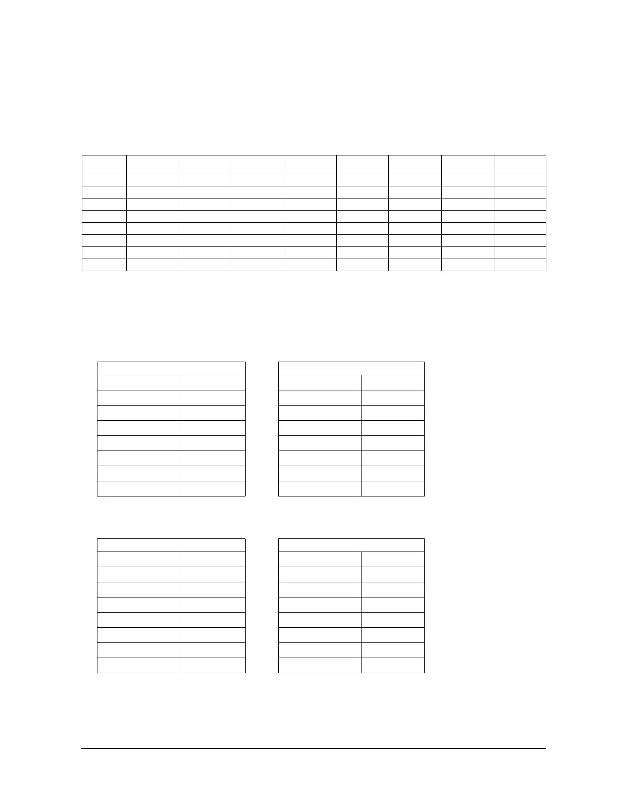
at P13 on the motherboard. Use the following table to identify the appropriate pin number:
4. If either signal is incorrect, use the following table and check the signal at P221, as it leaves the
CPU board. If the signal is bad at P221, replace the A18 CPU.
5. If both signals are correct, press the faulty hardkey or softkey while monitoring the KEYCOL or
KEYROW on the oscilloscope. The KEYCOL line should pulse low; the KEYROW line should
pulse high.
If either line does not function properly, replace the front panel board.
KEYCOL0 KEYCOL1 KEYCOL2 KEYCOL3 KEYCOL4 KEYCOL5 KEYCOL6 KEYCOL7
KEYROW0 softkey 3 N/A Cont Up N/A LF Out N/A I/Q Pulse
KEYROW1 softkey 2 Incr/Set Cont Down Ampl Ampl Menu Mode Setup Aux Fctn FM/ϕΜ
KEYROW2 softkey 1 Up N/A Freq Sweep List Mode Mux AM
KEYROW3 softkey 4 N/A N/A Right Arrow Help Save Recall Trigger
KEYROW4 softkey 6 N/A Local Hold Mod On/Off 4 5 6
KEYROW5 softkey 5 N/A Return Down Arrow N/A 7 8 9
KEYROW6 N/A N/A N/A Left Arrow RF On/Off 0 . +/-
KEYROW7 softkey 7 N/A Preset N/A N/A 1 2 3
KEYCOL pins should be a TTL high KEYROW pins should be a TTL low
KEYCOL0
P13
–1
KEYROW0
P13–17
KEYCOL1
P13
–3
KEYROW1
P13–19
KEYCOL2
P13
–5
KEYROW2
P13–21
KEYCOL3
P13
–7
KEYROW3
P13–23
KEYCOL4
P13
–9
KEYROW4
P13–25
KEYCOL5
P13
–11
KEYROW5
P13–26
KEYCOL6
P13
–13
KEYROW6
P13–24
KEYCOL7
P13
–15
KEYROW7
P13–22