1-14
Troubleshooting
Troubleshooting Assembly–Level Problems
5. If all the signals measured in Step 4 are good, go to Step 6.
If any of the signals measured in Step 4 are bad, check the following signals at P221 of the
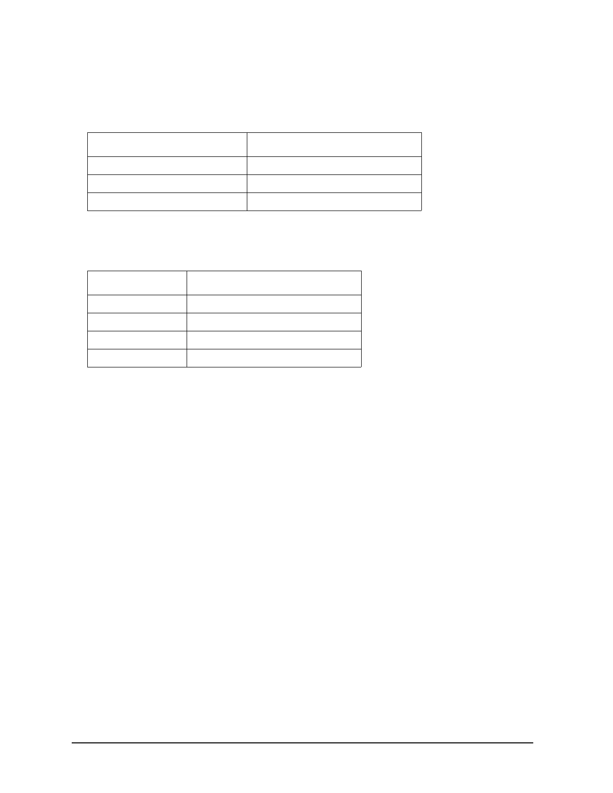
motherboard:
If any of these signals are bad, change the CPU board.
6. If all the signals measured in Step 4 are good, check the following signals at J9 of the power
switch. To access J9 the front panel must be removed from the chassis frame and laid face down.
If these signals are good, replace the LCD
If these signals are not good, replace the power switch/flat panel interface board.
Signal State
P221−14 VLCD approximately 21 Vdc
P221−53 LCD_ENABLE_H >3 Vdc
P221-1 to 13, 15, 41, 43, 45, 47, 49 to 52 Refer to Figure 1-1 on page 13.
Signal State
J9−7 VLCD approximately 21 Vdc
J9−4 LCD_ENABLE_H >3 Vdc
J9−55.2 Vdc
J9−1, 2, 3, 8 to 15 Refer Figure 1-1 on page 13.