1-25
Troubleshooting
Troubleshooting Assembly–Level Problems
Symptom: Instrument does not power up; power supply LEDs not on
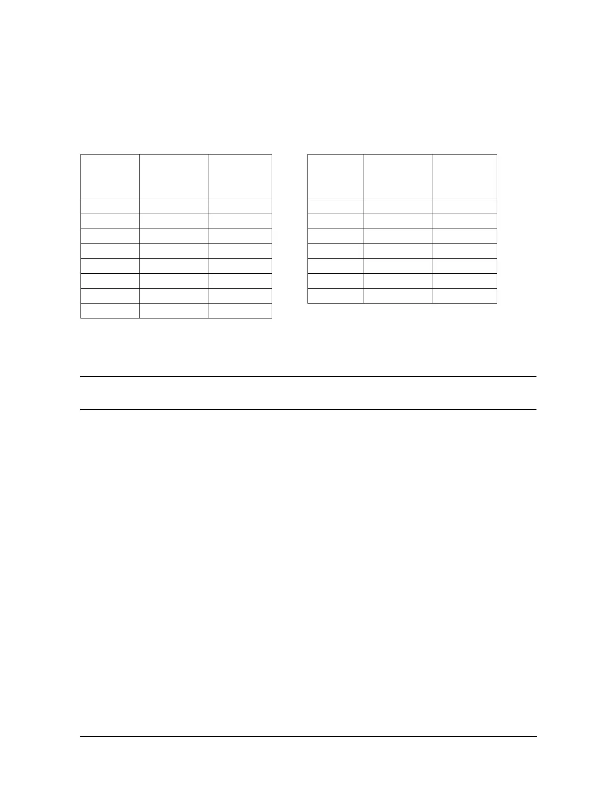
Checking Power Supplies Each of the power supplies has an LED on the bottom of the
motherboard (see Figure 1-2 on page 26 and Figure 1-3 on page 27). When the power supply is
functioning, the green LED lights. Use a DVM to measure the supplies on the motherboard, and
ensure they meet the following power supply specifications.
If a supply LED is not lit, or a measured voltage is less than the acceptable value, an assembly may
be loading down that supply. Using the appropriate Power Supply vs. Assembly Matrix, determine
where each supply is used, then use the following steps to isolate the defective assembly.
CAUTION Remove a minimum number of assemblies at one time. If the power supply does not
have a minimum load on it, the supply voltage increases to an overvoltage condition.
1. Turn off the instrument and remove one of the assemblies biased by the faulty supply.
2. Turn the instrument on and check the faulty supply. If the supply LED lights, replace the
assembly removed in Step 1. If not, continue with Step 3.
3. Turn the instrument off and reinstall the assembly removed in Step 1. Remove the next
assembly and see if the supply LED lights. Continue this process until the supply functions
properly.
4. Replace the last assembly that you removed.
Supply
Voltage
Acceptable
Voltage
(Vdc)
Maximum
Ripple
(mVpp)
Supply
Voltage
Acceptable
Voltage
(Vdc)
Maximum
Ripple
(mVpp)
+32 32 ± 0.96 10 +1.95 VD_1 1.95 ± 0.06 10
+15 15 ± 0.45 10 +1.95 VD_2 1.95 ± 0.06 10
+15 Standby 15 ± 0.45 20 +1.8 VD_1 1.8 ± 0.05 10
+10 10 ± 0.3 10 +1.8 VD_2 1.8 ± 0.05 10
+5.2 5.2 ± 0.16 10 –5.2 V2 –5.2 ± 0.16 10
+5.2 D 5.2 ± 0.16 20 –7.0 –7.0 ± 0.21 10
+3.4 D 3.4 ± 0.1 10 –15 –15 ± 0.45 10
+2.6 D 2.6 ± 0.08 10