Agilent N5181A/82A MXG Signal Generators User’s Guide 97
Basic Digital Operation (Option 651/652/654)
Using Waveform Markers
Using the EVENT Output Signal as an Instrument Trigger
One of the uses for the EVENT
output signal (marker signal) is to
trigger a measurement instrument.
You can set up the markers to start
the measurement at the beginning
of the waveform, at any single point
in the waveform, or on multiple
points in the waveform. To optimize
the use of the EVENT signal for
measurements, you may also need
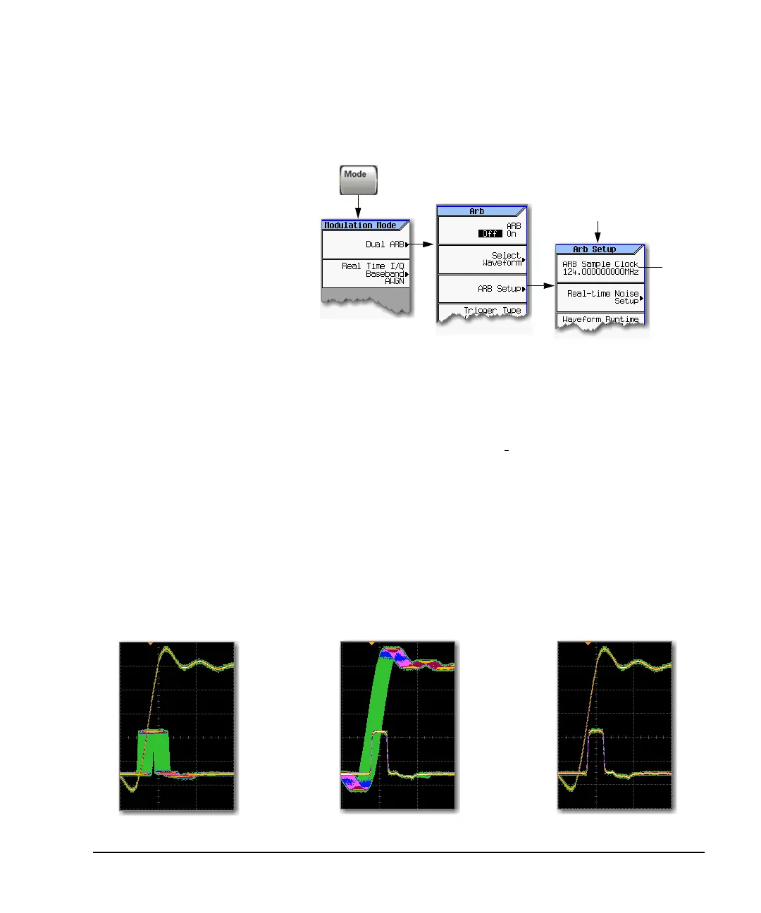
to adjust the sample rate. The
location of the sample rate setting
is shown in the figure at right.
The EVENT output signal can exhibit jitter of up to ±4 ns on the rising and falling edge. This jitter
can be minimized in either of two ways.
Method 1: Use a sample clock of 125 MHz/N where N is a positive integer and where 125 MHz/N can
be represented exactly on the display.
For example: 125 MHz, 62.5 MHz, 31.25 MHz, 25 MHz, and so on.
If the result cannot be represented exactly on the display, jitter will be present.
For example: N = 6 will result in jitter, because , which is truncated when
displayed.
Method 2: Select a sample clock and waveform length that spaces the markers by a multiple of 8 ns.
For example: A 200 point waveform with a marker on the first point and a sample clock of 50 MHz
provides a marker every 4 µs. Because 4 µs is a multiple of 8 ns, the jitter is minimized.
When the EVENT output signal exhibits jitter and it is used as a measurement trigger, it can cause
the waveform to falsely appear as having jitter. If this condition occurs, you can adjust the sample
rate to a value (see above) that does not cause the jitter appearance. To maintain the integrity of the
original waveform with a sample rate change, you will have to also recalculate the sample values. The
following figures illustrate the marker signal jitter and its affect on the waveform.
Sample
rate
setting
The settings in this menu
can be stored to the file
header, see page 78.
For details on each key, use key help as described on page 23.
125 MHz 6⁄ 20.833 MHz=
The jitter is gone with
an optimal sample rate
Waveform appears to exhibit jitter when
triggered using EVENT signal with jitter.
Oscilloscope triggering on waveform
Oscilloscope triggering on EVENT signal
Oscilloscope triggering on EVENT signal
EVENT output signal exhibits jitter
due to a non-optimal sample rate
 Loading...


