Agilent N5181A/82A MXG Signal Generators User’s Guide 125
Basic Digital Operation (Option 651/652/654)
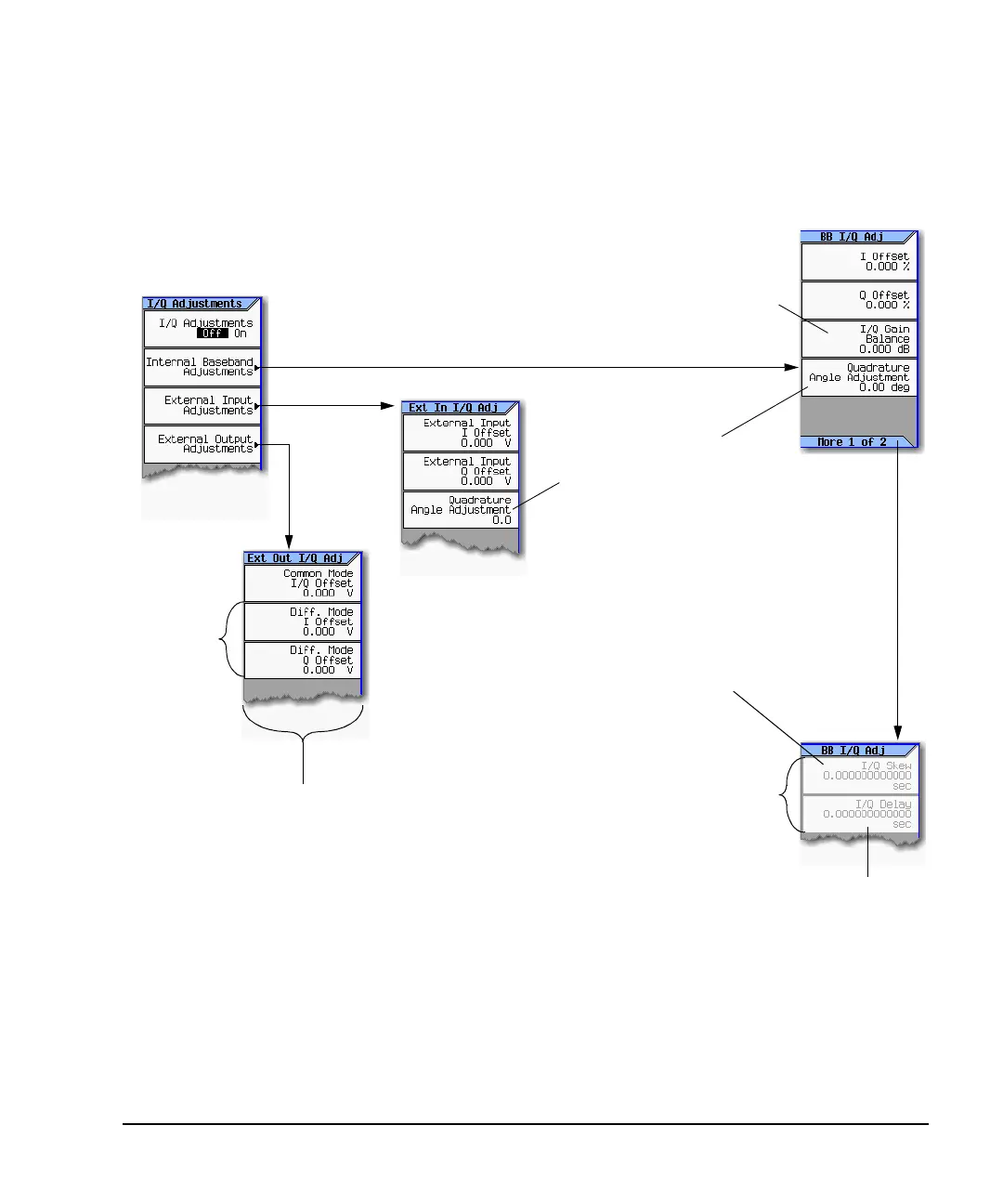
I/Q Adjustments
I/Q Adjustments
Use the I/Q Adjustments to compensate for or add impairments to the I/Q signal.
/Q > I/Q Adjustments >
Available only when a
waveform is playing.
Available only
with Option 1EL
Adjusts the I signal amplitude relative to the Q
signal amplitude. Use this as an internal
impairment, or to compensate for differences in
signal path loss that occur due to path
irregularities in the external I and Q output
cabling.
Offsets the phase of the Q signal
relative to the phase of the I signal.
The baseband quadrature
adjustment key is calibrated in units
of degrees. The external input
quadrature adjustment is not
calibrated.
The function provided by this key is
not the same as the function
provided by the I/Q Skew key.
Skew is typically used either to create impairments, or to
reduce error vectors on large bandwidth signals.
Provides a relative time delay correction between the I and
Q signals. The different signal paths traveled by the I and Q
signals result in time delay differences that show up as an
EVM error in large bandwidth modulated signals.
Adding an equal and opposite time delay (skew) in the I/Q
signals during baseband generation eliminates the time
delay error, correcting for any delays in signals that are
generated in the internal baseband generator.
Changes the absolute phase of both the I and Q signals wit
respect to triggers and markers.
Positive values add delay and negative values advance the
signals. This value affects both the baseband signal
modulated onto the RF and the external output signals (I an
Q). This setting cannot be used with constant envelope
modulation and it does not affect external I and Q inputs.
Offsets are typically used to either reduce carrier leakage, or to create
an impairment that simulates carrier leakage.
Common Mode I/Q Offset
This adjusts the DC offset of both I and Q signals simultaneously.
Diff Mode I Offset
This adjusts the DC offset level of the I and I-bar output signal. I and
I-bar cannot be adjusted independently.
Diff Mode Q Offset
This adjusts the DC offset level of the I and I-bar output signal. I and
I-bar cannot be adjusted independently.
 Loading...


