144 Agilent N5181A/82A MXG Signal Generators User’s Guide
Troubleshooting
RF Output
Signal Loss While Working with a Spectrum Analyzer
The effects of reverse power can cause problems with the RF output when you use the signal
generator with a spectrum analyzer that does not have preselection. Use an unleveled operating mode
(described on page 47).
A spectrum analyzer can have as much as +5 dBm LO feedthrough at its RF input port at some
frequencies. If the frequency difference between the LO feedthrough and the RF carrier is less than
the ALC bandwidth, the LO’s reverse power can amplitude modulate the signal generator’s RF output.
The rate of the undesired AM equals the difference in frequency between the spectrum analyzer’s LO
feedthrough and the signal generator’s RF carrier.
Reverse power problems can be solved by using one of the unleveled operating modes.
See:
• “ALC Off Mode” on page 47
and
• “Power Search Mode” on page 48
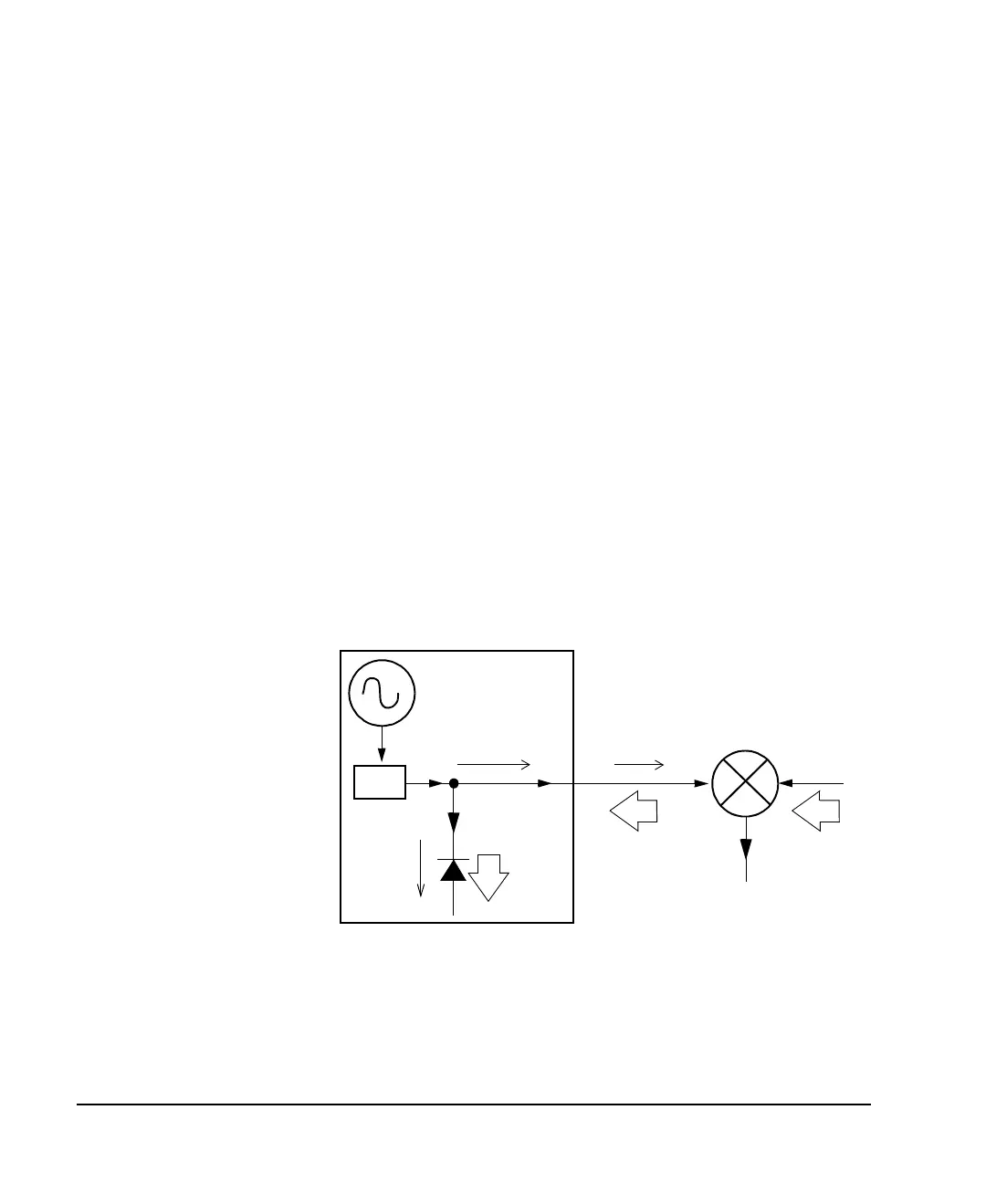
Signal Loss While Working with a Mixer
To fix signal loss at the signal generator’s RF output during low- amplitude coupled operation with a
mixer, add attenuation and increase the RF output amplitude.
The figure at right shows a
configuration in which the
signal generator provides a
low amplitude signal to a
mixer.
The internally leveled signal
generator RF output (and ALC
level) is −8 dBm. The mixer is
driven with an LO of +10 dBm
and has an LO- to- RF isolation
of 15 dB. The resulting
−5 dBm LO feedthrough
enters the signal generator’s
RF output connector and
arrives at the internal
detector.
Depending on frequency, it is
possible for most of this LO
feedthrough energy to enter the detector. Because the detector responds to its total input power
regardless of frequency, this excess energy causes the ALC to reduce the RF output. In this example,
the reverse power across the detector is actually greater than the ALC level, which can result in loss
of signal at the RF output.
Mixer
LO
ALC Level
= −8 dBm
RF Level
Control
Signal Generator
Output Control
Detector
measures
−8dBm
ALC level
Detector
measures
−5dBm
reverse
power
LO Feedthru
= −5 dBm
RF Output
= −8 dBm
LO Level
= +10 dBm
IF
Effects of Reverse Power on ALC
 Loading...


