Agilent N5181A/82A MXG Signal Generators User’s Guide 145
Troubleshooting
RF Output
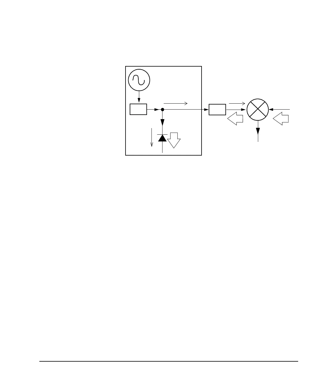
The solution at right shows a
similar configuration with the
addition of a 10 dB
attenuator connected between
the RF output of the signal
generator and the input of
the mixer. The signal
generator’s ALC level
increases to +2 dBm and
transmits through a 10 dB
attenuator to achieve the
required −8 dBm amplitude
at the mixer input.
Compared to the original
configuration, the ALC level
is 10 dB higher while the
attenuator reduces the LO
feedthrough (and the signal
generator’s RF output) by 10
dB. Using the attenuated
configuration, the detector is exposed to a +2 dBm desired signal versus the −15 dBm undesired LO
feedthrough. This 17 dB difference between desired and undesired energy results in a maximum
0.1 dB shift in the signal generator’s RF output level.
Mixer
LO
ALC Level/
RF Output
= +2 dBm
RF Level
Control
Signal Generator
Output Control
Detector
measures
+2 dBm
ALC level
Detector
measures
−15 dBm
reverse
power
LO Feedthru
= −5 dBm
RF Output
= −8 dBm
LO Level
= +10 dBm
IF
Reverse Power Solution
10 dB
ATTEN
 Loading...


