Agilent N5181A/82A MXG Signal Generators User’s Guide 121
Basic Digital Operation (Option 651/652/654)
I/Q Modulation
I/Q Modulation
The following factors contribute to the error vector magnitude:
• Differences in amplitude, phase, and delay between the I and Q channels
•DC offsets
The I/Q menu not only enables you to select the I/Q signal source and output, it also provides
adjustments and calibrations to compensate for differences in the I and Q signals.
See also, “Modulating the Carrier Signal” on page 34.
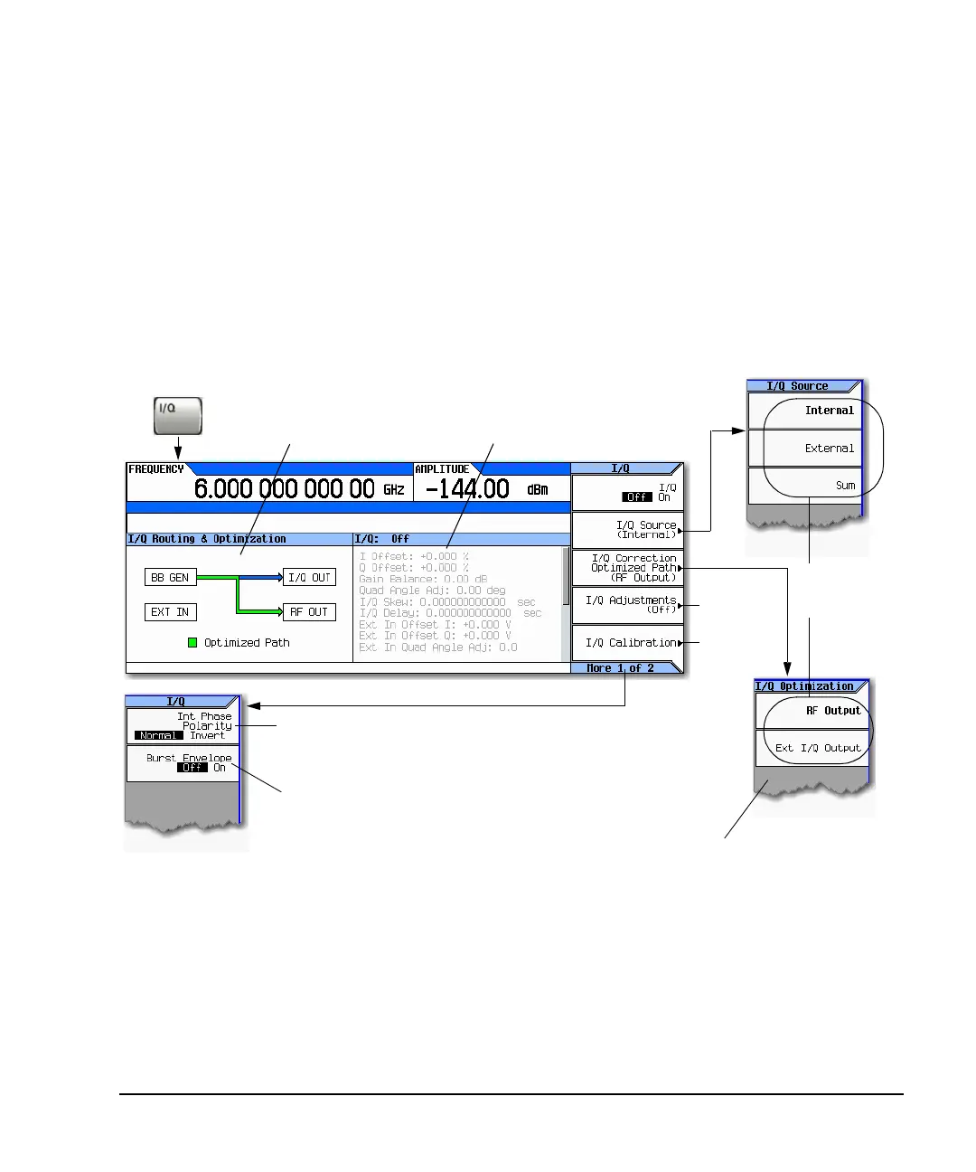
Figure 8-14 I/Q Display and Softkeys
These selections ar
reflected in the
I/Q Routing &
Optimization graphi
page 125
This panel displays the current
settings for the I/Q signal routing
and I/Q correction optimized path.
This panel displays the current status and settings
of the I/Q adjustments. Use the Page Up and
Page Down keys to scroll through these
parameters. Grey indicates an inactive (off)
adjustment.
Used only with internally generated,
bursted modulation formats.
Enables/disables the RF burst modulator.
or details on each key, use key help
s described on page 23.
Each path requires different optimization values;
when you select a path, you are selecting the
unique optimization values required by that path.
The signal generator applies the selected
optimization values to both paths, which impairs
the unselected path.
Inverts an internally generated Q signal, so that the
I component lags the Q component by 90 degrees.
page 127
 Loading...


