7
Chapter 1: PlateLoc introduction
PlateLoc User Guide
Connection panel
About this topic This topic describes the connection panel on the back of the PlateLoc.
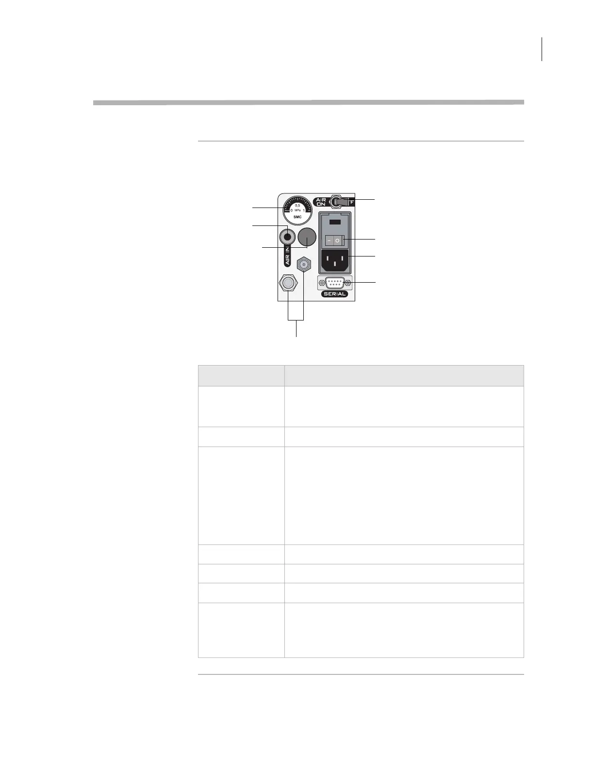
Description The following diagram shows the connection panel that is located on
the back of the PlateLoc. The table below the diagram describes each
component on the panel.
Air on/off switch
Power switch
AC power entry
Serial port
Air flow gauge
Air-input fitting
Argon-input fitting
(Gas-Purging
PlateLocs only)
For Velocity11 service use only
Feature Description
Air flow gauge Indicates the presence of air flow inside the PlateLoc.
Compressed air is used to move pneumatic
components inside the PlateLoc.
Air-input fitting Connects the air tubing to the PlateLoc.
Argon-input fitting
(Gas-Purging
PlateLocs only)
Connects the argon tubing to the Gas-Purging PlateLoc.
Argon is used to displace air in the plate, thereby
removing oxygen and moisture.
Note: There is no on/off switch for argon. Argon starts to
fill the sealing chamber automatically when a seal cycle
starts. For safety reasons, the argon stops filling the
sealing chamber automatically just before the seal is
applied.
Air on/off switch Turns on or off the air flow into the PlateLoc.
Power switch Turns on or off the power to the PlateLoc.
AC power entry Connects the power cord to the PlateLoc.
Serial port Connects the serial cable from the controlling computer
to the PlateLoc.
Use this port when installing the PlateLoc in a lab
automation system.
 Loading...