33
MT- S
2.4GHZ FH4T RADIO SYSTEM USER'S GUIDE
Telemetry System with Sanwa Synchronized Link Support
Section Continued on Next Page
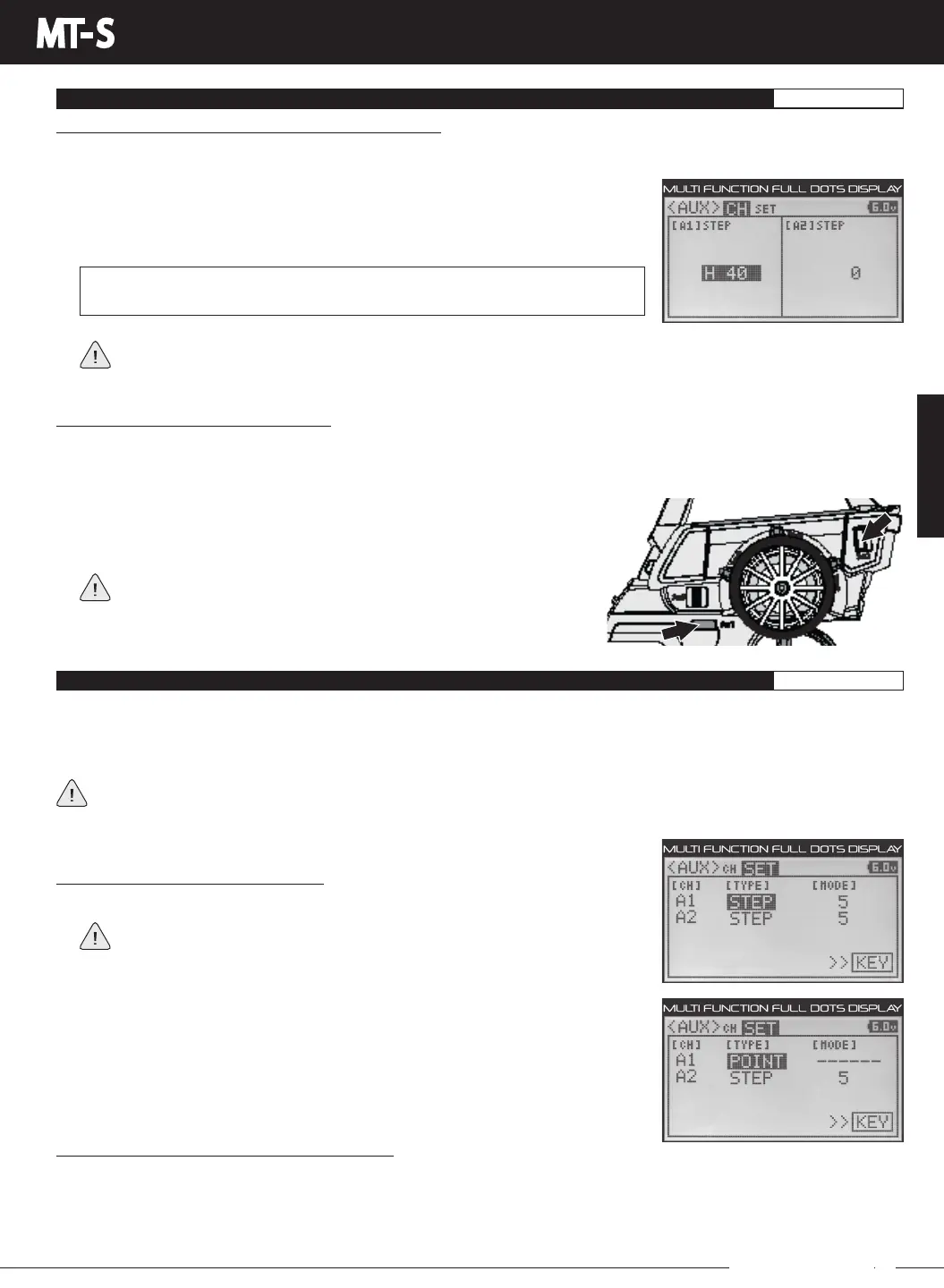
The Step Auxiliary Position value will change in increments that you programmed in the Step Mode Value section
previously. If you need the Step Auxiliary Position value to change in different increments to achieve a different value,
change the Step Mode value to something different (e.g. 1, 2, 5, etc.).
STEP AUX MENU
STEP AUXILIARY
AUX
Changing the Step Auxiliary Position Value, Continued:
3) Press the UP or DOWN keys to choose A1 STEP or A2 STEP, depending on which Auxiliary channel you want to change the
Step Auxiliary Position value for.
AUX MENU
POINT AUX MENU
POINT AUXILIARY
AUX
The Point Auxiliary function allows you to program the Auxiliary 1 (Channel 3) and Auxiliary 2 (Channel 4) servos to move up to
3 different Points along its travel, then cycle through those Points using one of the Trim Switches or Auxiliary Switch Sw3. For
example, if your model requires a separate 3-position switch to operate a feature, such as a multi-position wing, the Point Auxiliary
function can be customized to control this.
This section details programming the Point Auxiliary function for both Auxiliary 1 (Channel 3) and Auxiliary 2 (Channel 4),
since programming each of them is the same. Choose either CH A1 for Auxiliary 1 (Channel 3) or CH A2 for Auxiliary 2
(Channel 4), depending on which channel you want to program the Point Auxiliary function for.
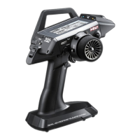
Choosing the Point Auxiliary Function:
1) From within the AUX menu, press the UP or DOWN keys to highlight AUX SET.
If the cursor isn't flashing over Channel/Options, press the BACK key, then
press the UP or DOWN keys to highlight the AUX SET menu Option.
2) Press the ENTER key, then press the UP or DOWN keys to highlight either CH A1
TYPEorCHA2TYPE,dependingonwhichAuxiliarychannelyouwanttoprogram,
either Auxiliary 1 (Channel 3) or Auxiliary 2 (Channel 4).
3) Press the ENTER key, then press the UP or DOWN keys to choose the POINT option
for the selected channel.
4) Press the ENTER key, then press the UP or DOWN keys to change the Step Auxiliary
Position value. Increasing the value toward the High side (H) or Low side (L) will
cause the Auxiliary servo to travel to that specific position when you toggle the Step
Auxiliary function using an Auxiliary Switch.
AUX CH STEP setting range is H100 to L100. The default setting for both channel
is 0. This value is a percentage of Auxiliary servo travel.
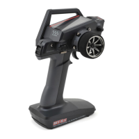
Controlling the Step Auxiliary Function:
Auxiliary Switch Sw3 and a Trim Switch are not suitable for controlling the Step Auxiliary function. The Step Auxiliary function
is better suited to be controlled by Auxiliary Switch Sw1 or Sw2, since these are 2-position switches. If you haven't already
Assigned the AUX1 STEP or AUX2 STEP function to one of these Auxiliary Switches, you should do that now. For more information,
seetheKEYASSIGNMenusectiononpages56through60.
1) Toggle Auxiliary Switch Sw1 or Sw2 to move the Auxiliary servo back and
forth between neutral and its programmed position.
If the servo moves the wrong direction, program the Step Auxiliary
Position value opposite of what you currently have (i.e. change from
H50 to L50).
Choosing the Key Option (Key Assign Function):
In the default configuration, AUX1 POINT is controlled by Auxiliary Switch Sw2 and AUX2 POINT is controlled by Auxiliary Switch
Sw3.TheKeyoptionisashortcuttotheKEYASSIGNmenu,whichallowsyoutoAssignthePointAuxiliaryfunctiontoadifferent
Auxiliary Switch or a Trim Switch. The Point Auxiliary function is best suited to be controlled by Auxiliary Switch Sw3 or a Trim
Switch. Auxiliary Switch Sw1 and Sw2 are not suitable for controlling the Point Auxiliary function, since these are
2-position switches.