9
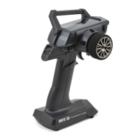
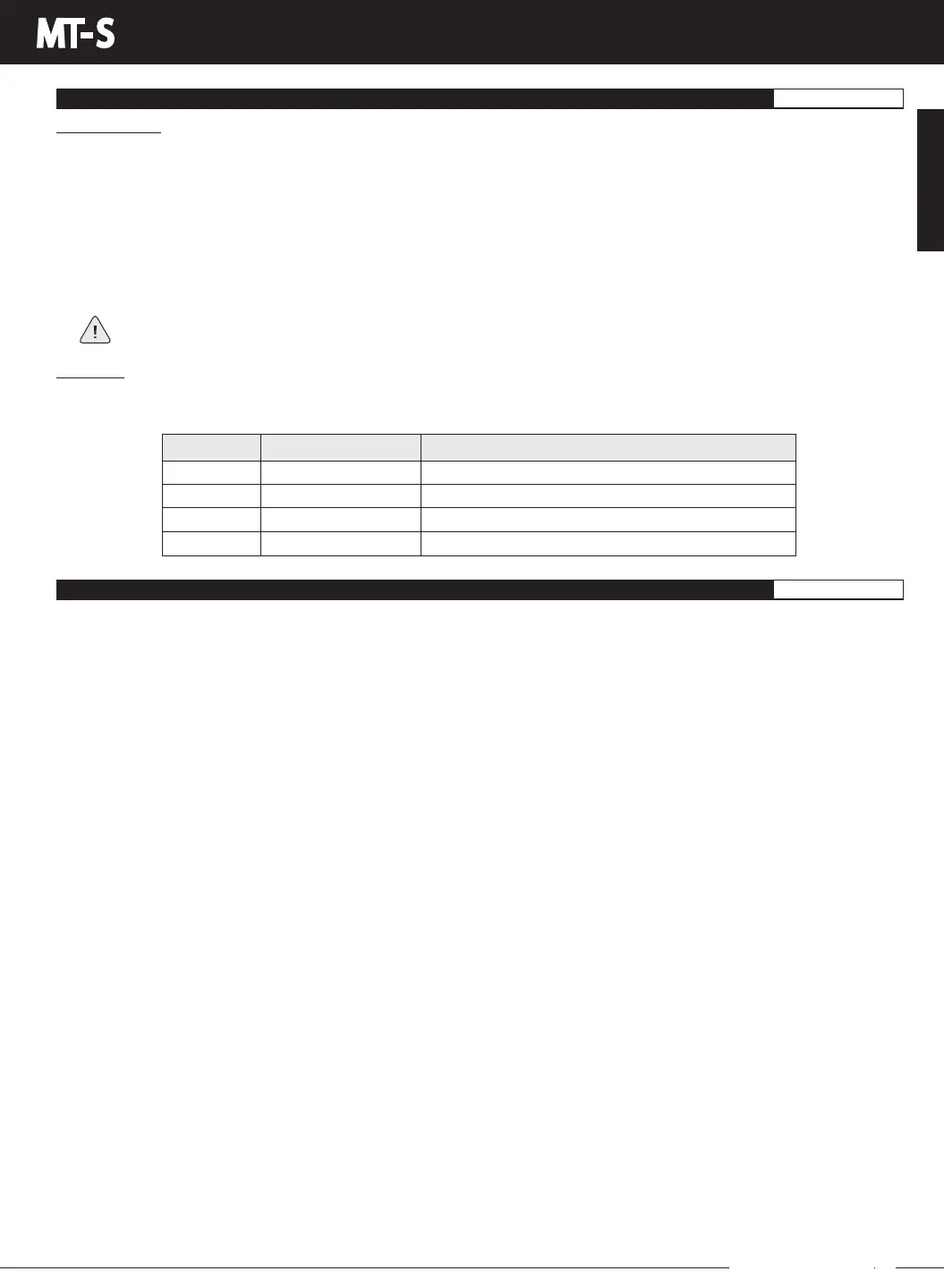
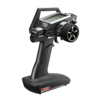
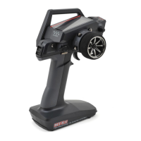
MT- S
2.4GHZ FH4T RADIO SYSTEM USER'S GUIDE
Telemetry System with Sanwa Synchronized Link Support
Section Continued on Next Page
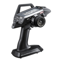
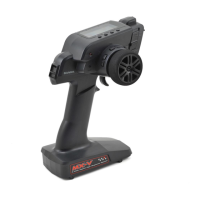
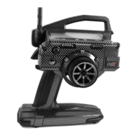
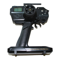
Antenna: Transmits the signal from the transmitter to the receiver in the model. Never touch the Antenna during use. Doing
so may result in a weakened RF signal or complete loss of control of your model. The receiver also features an antenna that
receives the RF signal from the transmitter.
Auxiliary Switch: The transmitter features three separate Auxiliary Switches (Sw1, Sw2 and Sw3). Each Auxiliary Switch is
programmable and will perform a different function depending on what function is assigned to it. Auxiliary Switch (Sw1) is a
push-button switch, Auxiliary Switch (Sw2) is a 2-position sliding switch and Auxiliary Switch (Sw3) is a 3-position sliding switch.
BACK Key: Pressing the BACK Key returns the Programming Cursor to the previous menu. Press and HOLD the BACK Key to
return to the STATUS screen.
Battery Compartment: Houses the four 'AA' Alkaline cells that power the transmitter. Alternatively, the transmitter can be
powered using four 'AA' NiMH rechargeable batteries or a 2S LiPo or 2S LiFe battery pack.
Bind Button: Used in the process of binding the transmitter and receiver.
Bind LED: Displays the current status of the receiver.
DOWN Key: Pressing the DOWN Key scrollsbetweentheSTATUSandTELEMETRYscreens,scrollstheProgrammingCursor
DOWN or LEFT and Decreases Programming Values.
ENTER Key: Pressing the ENTER Key opens the selected menu or Programming Option. Press and HOLD to reset the selected
Programming Option to its default value.
Grip: The Grip is molded in an ergonomic shape for Increased comfort, control and feel.
LCD Screen: The heart of the programming and display features of the transmitter. All programming and transmitter display
functions are shown on the LCD screen.
LED Condition Indicator: Displays the current RF signal output status of the transmitter, in addition to various other transmitter
conditions.
Power Switch: Turns the transmitter ON and OFF.
Steering Wheel: Proportionally operates the model's right and left steering control. The Steering Wheel features a foam grip for
Increased comfort, control and feel. In addition, the Steering Wheel spring tension can be adjusted.
Steering Wheel Tension Adjustment Screw: Used to adjust the spring tension of the Steering Wheel to best suit the feel of
the user.
Throttle Trigger: Controls the speed of the model, both forward and backward, or the model's brake. The Throttle Trigger position
and spring tension can both be adjusted.
Throttle Trigger Tension Adjustment Screw: Used to adjust the spring tension of the Throttle Trigger to best suit the feel of
the user.
RECEIVER OVERVIEW DIAGRAM, CONNECTIONS AND MOUNTING
GENERAL
Mounting Tips:
• Forthebestreceptiondistancepossible,thetopofthereceiverMUSTbetowardthetopofyourmodel(asshowninthe
illustration on the previous page) and the receiver should be mounted as high as possible in your model.
• The receiver can be mounted inside a receiver box, however, when mounting inside a receiver box, the antenna position
will be lower and the reception distance may be shorter.
• The receiver should be mounted securely to your model using a piece of double-sided foam tape to help minimize vibration.
It's okay to wrap the receiver in protective foam rubber, if desired. Doing so will not affect the reception distance.
• Dototheinternalantennaposition,this receiver is not suitable for use in an R/C boat. It should be used in R/C cars and
trucks only.
As a safety precaution, set your model on a stand so the wheels are off the ground before turning on your radio control
system or connecting your motor for the first time.
Bind LED:
The Bind LED on the receiver can be used to determine receiver condition at a glance. The Bind LED will alert you to various
receiver conditions, as shown in the table below.
Blue
Blue
Red & Blue
Red
Receiving RF Signal
Binding Operation
Receiver Battery Fail Safe Activates
No RF Signal After Receiver Battery Fail Safe Activates
LED COLOR
RECEIVER STATUS
LED CONDITION
ON
Slow Flash/Fast Flash
Flash
ON
TRANSMITTER AND RECEIVER OVERVIEW DIAGRAM DESCRIPTIONS
GENERAL
GENERAL