7
MT- S
2.4GHZ FH4T RADIO SYSTEM USER'S GUIDE
Telemetry System with Sanwa Synchronized Link Support
Section Continued on Next Page
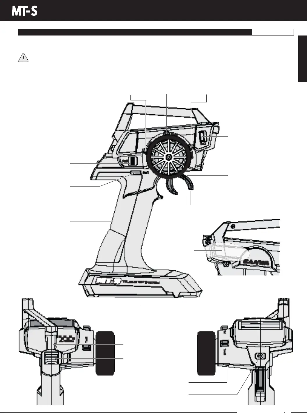
Use the diagrams in this section to familiarize yourself with the layout of your transmitter. Descriptions of these features can be
found in the Transmitter and Receiver Overview Diagram Descriptions section on pages 9 and 10.
The transmitter antenna is mounted internally and is located in the left front side portion of the transmitter, below the
carrying handle Do NOT cover this area in any way during use! Doing so can block the RF signal, resulting in loss of
control of your model. During use, hold the transmitter so that its orientated as close to vertical as possible at all times. This
provides the best RF signal between the transmitter and the receiver. Try not to ever 'follow' your model with the transmitter, as
this can result in a weakened RF signal.
TRANSMITTER OVERVIEW DIAGRAMS
GENERAL
Antenna
(Inside Case)
Trim Switch
(Trm1)
Battery Compartment
Auxiliary Switch (Sw2)
Throttle Trigger
Grip
Auxiliary Switch (Sw3)
Trim Switch
(Trm3)
Trim Switch
(Trm2)
Throttle Trigger Tension
Adjustment Screw
RIGHT SIDE VIEW
Throttle Trigger Position
Adjustment Screw
Steering Wheel Tension
Adjustment Screw
FRONT VIEW
Wrist Strap Anchor
Power Switch
BACK VIEW
Auxiliary Switch (Sw1)
GENERAL