21
AIRZONE CONTROL MODULE OF RADIANT ELEMENTS (AZCE6OUTPUT8)
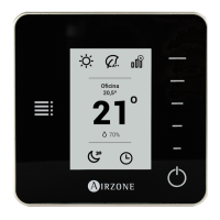
Assembly
This module is mounted on DIN rail (Fig. 17). It module is externally powered at 110/230 Vac. It is should be placed and mounted
in accordance with the current electrotechnical regulations.
Fig. 17
Note: To take the module away, pull the reed down to release it.
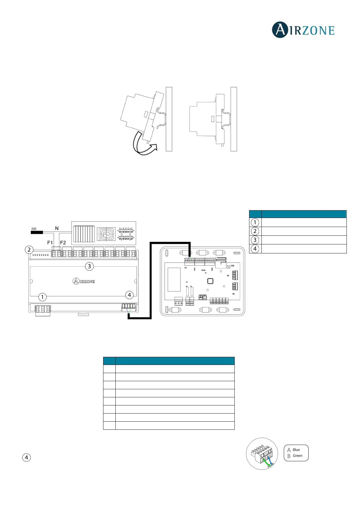
Connection
The control module of radiant elements is a device that connects to the Airzone connection bus of the main board (Fig. 18).
Control relay specs: I
max
= 10 A at 110/230 Vac, voltage-free.
Note that to control elements with a greater power, it is recommended to use contactors in accordance with the power
required. Remember to connect the neutral connector directly from the circuit to the element to be controlled.
Operation of the relays:
It has a 5-pin terminal to connect it to the Airzone connection bus of the main board
. Attach the wires with the terminal screws following the color code (Fig. 19).
Power supply
Radiant element demand - Zone 1
Radiant element demand - Zone 2
Radiant element demand - Zone 3
Radiant element demand - Zone 4
Radiant element demand - Zone 5
Radiant element demand - Zone 6
Radiant element demand - Zone 7
Radiant element demand - Zone 8
 Loading...