16
ASSEMBLY AND CONNECTION
MAIN CONTROL BOARD (AZCE6FLEXA3 / AZCE6IBPRO6)
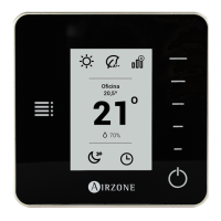
Assembly
The production control board is supplied in a box to be screwed to the wall (Fig. 1). It is
should be placed and mounted in accordance with the current electrotechnical regulations.
For the mounting of the main control board, follow the following steps:
• Locate the control board close to the unit to be controlled.
• Unscrew the cover securing the back part to the wall.
• Make all the connections and screw the cover again.
In Flexa 3.0 systems, it is possible to add a remote zone ON/OFF module to the main control
board (AZCE6ONOFF6Z). To do this, insert the module in the corresponding connectors of the main board (Fig. 2).
Fig. 2
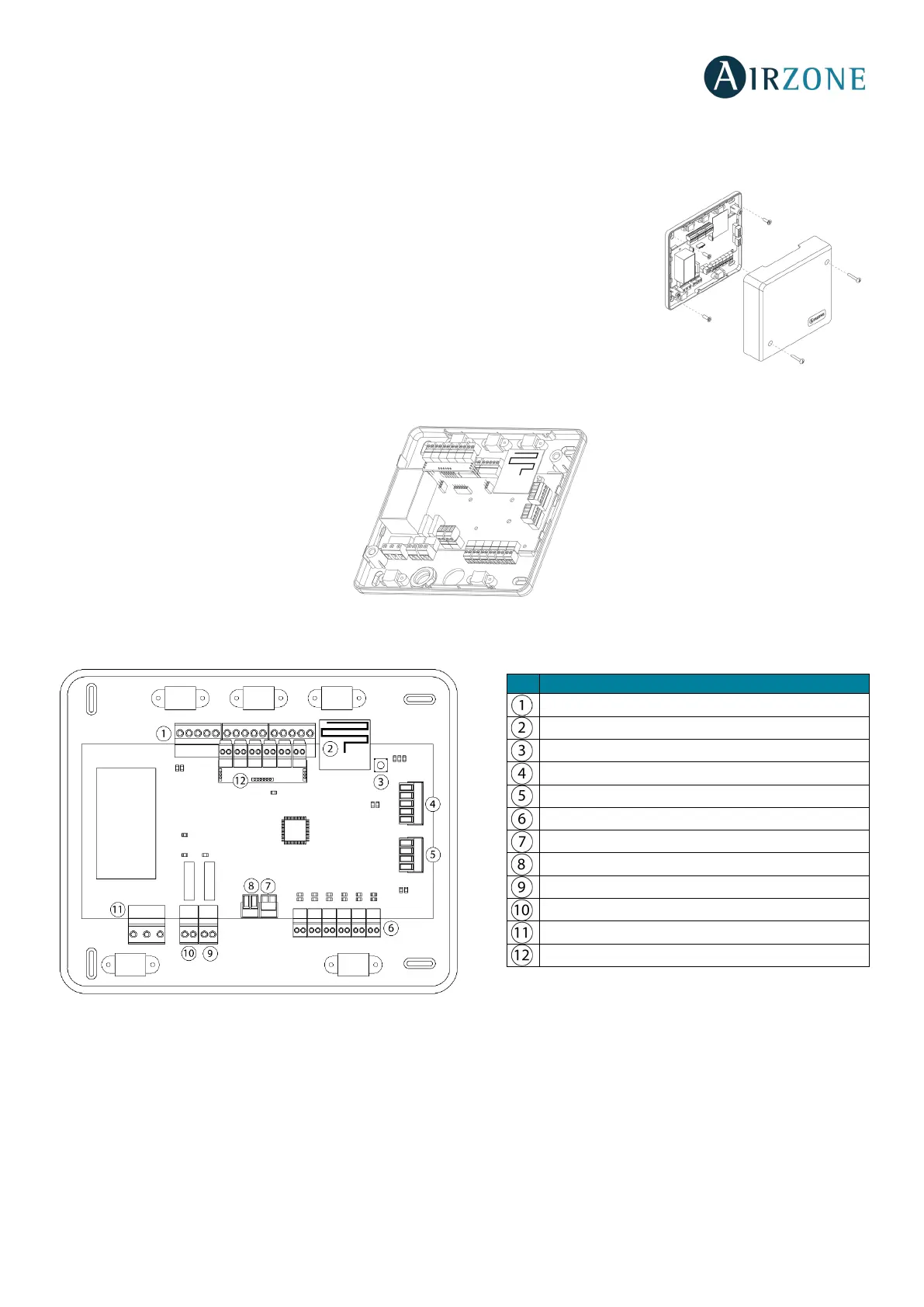
Connection
Fig. 3
Airzone connection bus connectors
The Airzone connection bus allows you to connect all the internal components dependent on the main board to control up to
6 zones (or 8 with the expansion module AZCE6EXP8Z). These are the elements that can be connected:
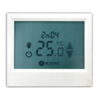
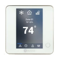
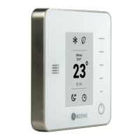
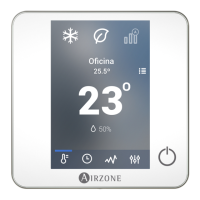
- Blueface (AZCE6BLUEFACEC), Think (AZCE6THINKC) and Lite (AZCE6LITEC) thermostats.
- Airzone Control module of radiant elements (AZC3POUTPUTC6).
- Expansion module (AZCE6EXP8Z).
Wireless Module
SW1
AC unit bus
Damper outputs
Alarm input (normally closed)
Temperature probe
CMV/Boiler
Power
On/Off module (Only AZCE6IBPRO6)
 Loading...