IEEE 1588 Analysis
211
plied by special Announce messages generated periodically by Ordinary and
Boundary Clocks.
2. Clock synchronization. Slave clocks may have a positive or negative offsets when
compared with their masters and latency from masters to slaves is also unknown.
PTP devices start a procedure to compute latencies and offsets. These parame-
ters will be used to adjust timing in slave devices.
9.1.3. The Synchronization Mechanism
Once the master and slave hierarchies have been established, by observing the clock
property information contained in Announce messages sent by PTP devices, the
synchronization process starts.
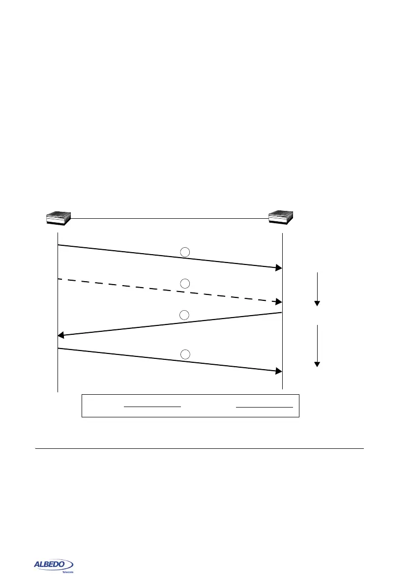
Before synchronization between the master and the slave clock has been achieved, it
may exist a frequency offset between both clocks. This offset is computed with the help
of the Sync message. Sync messages are sent periodically by the master to upgrade
offset information in the slave. Sync messages may carry an accurate times-tamp
indicating the departure time of the own message but this requires timestamping
hardware which may not always be available. To avoid dedicated hardware Follow_Up
Figure 9.1: Sync and Delay request-response mechanisms used by the PTP. The basic
parameters of Latency and Offset are computed from the t1, t2, t3 and t4 timestamps.
Sync1
Master
device
Slave
device
Follow_Up2
Delay_Req2
Delay_Resp4
Timestamps
collected
t1
t2
t3
t4
Offset =
(t2-t1)-(t4-t3)
2
Latency =
(t2 - t1) + (t4 - t3)
2
t1, t2
t1, t2, t3
t1, t2, t3, t4



 To Next Page