Synchronous Ethernet Analysis
265
1. Make sure that your tester is connected to the network in pass-through mode. The
physical layer must be up and working in ports A and B (See section 4.1.1).
Note: if you are working with the 1000BASE-T interface, force the master role in
the test Port A and slave role in test Port B. Also, you have to disable the 100-FD
and 10-FD auto-negotiation options for both ports (See section 2.2.3).
2. From the Home panel, go to CONFIG,
The test port setup panel is displayed.
3. Configure Mode to IP Through.
4. Go to Reference clock.
5. Configure Input clock to Ethernet (Port B).
6. From the port setup panel, now go to Wander generator.
7. Configure the Frequency deviation (ppm) with the frequency offset you want to
generate between -125 and 125 ppm.
The unit adds an offset to the frequency detected in Port B. This offset is transmit-
ted to test port A.
10.7.ESMC Generation and Analysis
The test unit can be configured to generate and analyse the ESMC in a Synchronous
Ethernet interface. Specifically, Test ports are allowed both to generate and monitor the
ESMC. The correct ESMC generation procedure is as follows:
1. Make sure that your tester is connected to the network. The physical layer must
be up and working in the correct test interface (See section 4.1.1).
2. From the Home panel, go to CONFIG,
The test port configuration panel is displayed.
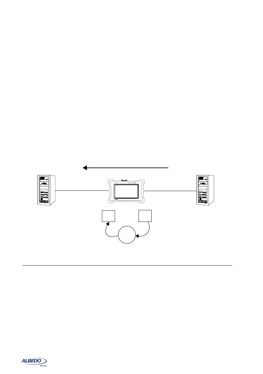
Figure 10.5: With the help of xGenius it is possible to generate frequency offset in pass-
through mode to stress the network.
Synchronization
+ 10
f0 = fi + 10 ppm
Port B
Port A
fi
TX
RX
ppm
xGenius