76 Rockwell Automation Publication 1756-UM022D-EN-P - May 2017
Chapter 5 Add, Configure, Monitor, and Replace CIP Safety I/O Devices
• Configuration signature
See page
85 for information on when the configuration signature is set
automatically and when you need to set it.
• Reaction time limit
See page
79 for information on setting the reaction time limit.
• Safety input, output, and test parameters complete the module
configuration
You can configure safety I/O devices via the GuardLogix® controller by using
the Logix Designer application.
Configure Safety I/O Devices
Add the safety I/O device to the communication module under the I/O
Configuration folder of the controller project.
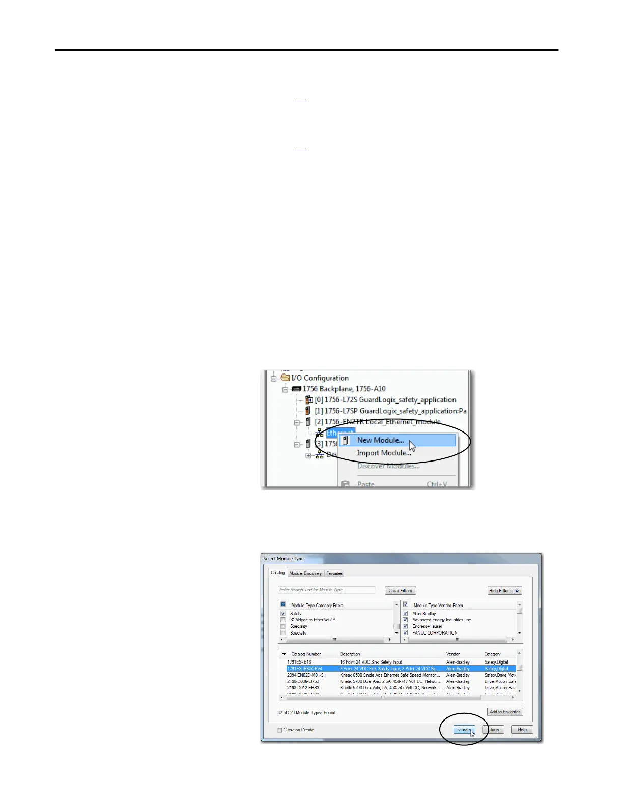
1. Right-click the DeviceNet or Ethernet network and choose New
Module.
2. From the Catalog tab, select the safety I/O device.
TIP Safety I/O devices support standard and safety data. Device configuration
defines what data is available.
TIP You cannot add or delete a safety I/O device while online.
TIP Use the filters to reduce the list of modules to choose from.

 Loading...


