138 Rockwell Automation Publication 2094-UM001J-EN-P - March 2017
Chapter 6 Configure and Start the Kinetix 6000 Drive System
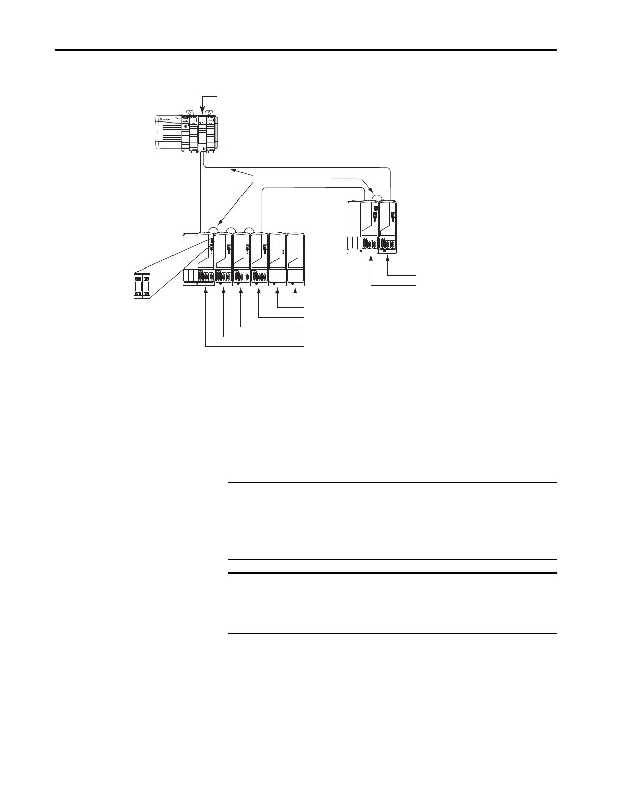
Figure 80 - Node Addressing Example 1
In Example 1, the Kinetix 6000 (6-axis) drive system 1 power rail contains one
IAM module, three AM modules, one shunt module, and one slot-filler
module. The shunt module and slot-filler modules are not assigned a Sercos
node address, but the system identifies them with a slot location.
Kinetix 6000 (2-axis) drive system 2 power rail contains one IAM module and
one AM module. The base node address of the (system 2) IAM module must
be set for an address of ≥007.
SERCOS interface
TM
Tx (rear)
Rx (front)
OK
CP
0 1
Kinetix 6000 Drive
System 2
(2-axis power rail)
06 = Slot-filler Module slot location
05 = Shunt Module slot location
04 = AM Module (axis 4) node address
03 = AM Module (axis 3) node address
02 = AM Module (axis 2) node address
01 = IAM Module (axis 1) base node address
Logix5000 Controller
(ControlLogix® controller is shown)
Sercos Fiber-optic Ring
1756-MxxSE Sercos
interface Module
08 = AM module (axis 2) node address
07 = IAM module (axis 1) base node address
Kinetix 6000 Drive
System 1 (6-axis power rail)
Receive
Receive
Trans mit
Transmit
Transmit
Receive
Base Node Address
Switches
IMPORTANT The node address for each axis module is determined by the base node-
address switch setting on the IAM module.
Do not position axis modules to the right of shunt or slot-filler modules. The
added distance between non-adjacent axes can increase electrical noise and
impedance, and requires longer fiber-optic cable lengths.
IMPORTANT Slot-filler modules must be used to fill any unoccupied slot on the power
rail. However, you can replace slot-filler modules with AM modules or the
2094-BSP2 shunt module (maximum one 2094-BSP2 shunt module per
power rail).
 Loading...


