64 Rockwell Automation Publication 2094-UM001J-EN-P - March 2017
Chapter 4 Connector Data and Feature Descriptions
Auxiliary Feedback Connector Pinout
For TTL devices, the position count increases when A leads B. For sinusoidal
devices, the position count increases when cosine leads sine.
Table 30 - Stegmann Hiperface (SRS and SRM only)
Table 31 - TTL or Sine/Cosine with Index Pulse
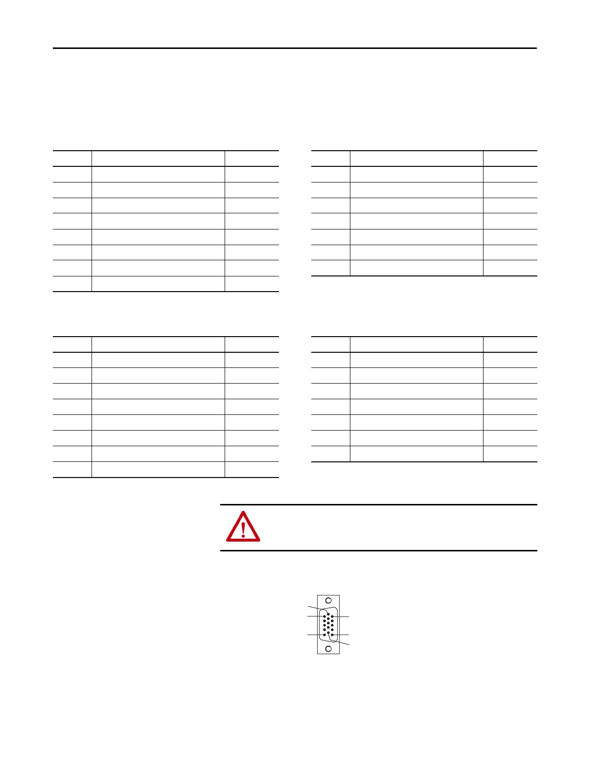
Figure 28 - Pin Orientation for 15-pin Auxiliary Feedback (AF) Connector
AF Pin Description Signal AF Pin Description Signal
1 Sine differential input+ SIN+ 9 Reserved –
2 Sine differential input- SIN- 10 Hiperface data channel DATA-
3 Cosine differential input+ COS+ 11 Reserved –
4 Cosine differential input- COS- 12 Reserved –
5 Hiperface data channel DATA+ 13 Reserved –
6 Common ECOM 14 Encoder power (+5V) EPWR_5V
(1)
7 Encoder power (+9V) EPWR_9V
(1)
15 Reserved –
8Reserved –
(1) Determine which power supply your encoder requires and connect to only the specified supply. Do not make connections to both.
AF Pin Description Signal AF Pin Description Signal
1 A+ / Sine differential input+ A+ / SIN+ 9 Reserved –
2 A- / Sine differential input- A- / SIN- 10 Index pulse- I-
3 B+ / Cosine differential input+ B+ / COS+ 11 Reserved –
4 B- / Cosine differential input- B- / COS- 12 Reserved –
5 Index pulse+ I+ 13 Reserved –
6 Common ECOM 14 Encoder power (+5V) EPWR_5V
(1)
7 Encoder power (+9V) EPWR_9V
(1)
15 Reserved –
8Reserved –
(1) Determine which power supply your encoder requires and connect to only the specified supply. Do not make connections to both.
ATTENTION: To avoid damage to components, determine which power
supply your encoder requires and connect to either the 5V or 9V supply, but
not both.
Pin 1
Pin 11
Pin 10
Pin 5
Pin 6
Pin 15
 Loading...


