EasyManuals Logo

Allen-Bradley Kinetix 6000 User Manual

Allen-Bradley Kinetix 6000
290 pages
To Next Page IconTo Next Page
To Previous Page IconTo Previous Page
Page #96 background imageLoading...
Page #96 background image
96 Rockwell Automation Publication 2094-UM001J-EN-P - March 2017
Chapter 5 Connect the Kinetix 6000 Drive System
For mounting bracket dimensions, refer to the 2094 Mounting Brackets
Installation Instructions, publication 2094-IN008
.
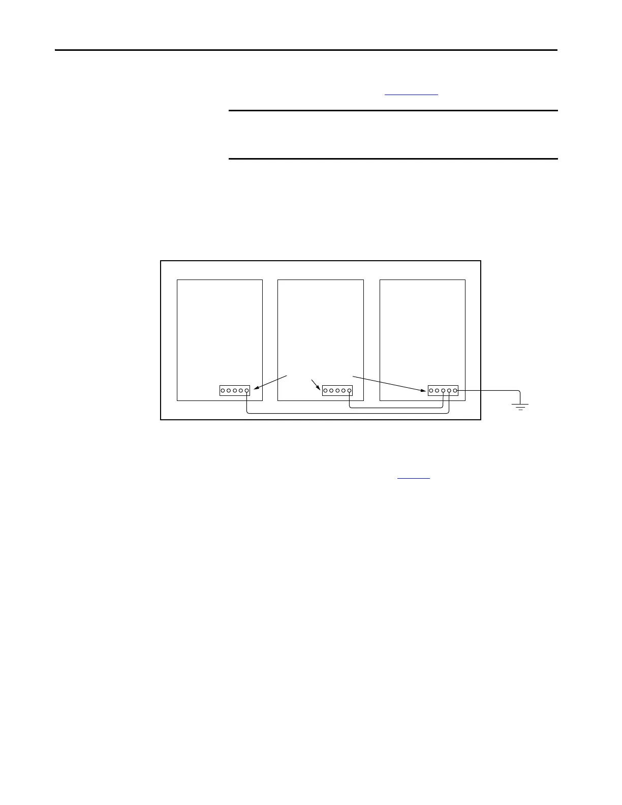
Ground Multiple Subpanels
In this figure, the chassis ground is extended to multiple subpanels.
Figure 48 - Subpanels Connected to a Single Ground Point
High-frequency (HF) bonding is not illustrated. For HF bonding information,
refer to Bonding Multiple Subpanels on page 36
.
IMPORTANT When 2094 mounting brackets are used to mount the power rail or LIM
module over the AC line filter, the braided ground strap must be removed
from the power rail and attached to a mounting bracket ground stud.
Follow NEC and
applicable local codes.
Bonded Ground Bus
Ground Grid or Power
Distribution Ground

Table of Contents

Other manuals for Allen-Bradley Kinetix 6000

Questions and Answers:

Question and Answer IconNeed help?

Do you have a question about the Allen-Bradley Kinetix 6000 and is the answer not in the manual?

Allen-Bradley Kinetix 6000 Specifications

General IconGeneral
Control TypeDigital
FeedbackResolver, Encoder
Protection RatingIP20
Power Range0.4…22 kW
CommunicationEthernet/IP
Ambient Temperature0°C to 50°C
AxisSingle-axis, Multi-axis
SafetySafe Torque-Off
Control ModesVelocity, Torque, Position
Relative Humidity5% to 95% (non-condensing)
Vibration Resistance5.9 m/s² (0.6 g) from 10 Hz to 500 Hz
Shock Resistance15 g, 11 ms
Storage Temperature-40°C to 70°C

Related product manuals