EasyManuals Logo

Allen-Bradley Kinetix 6000 User Manual

Allen-Bradley Kinetix 6000
290 pages
To Next Page IconTo Next Page
To Previous Page IconTo Previous Page
Page #184 background imageLoading...
Page #184 background image
184 Rockwell Automation Publication 2094-UM001J-EN-P - March 2017
Chapter 8 Remove and Replace the Kinetix 6000 Drive Modules
8. Verify that the system is operating properly.
Remove the Power Rail
This procedure assumes you have removed all modules from the power rail.
Follow these steps to remove the power rail.
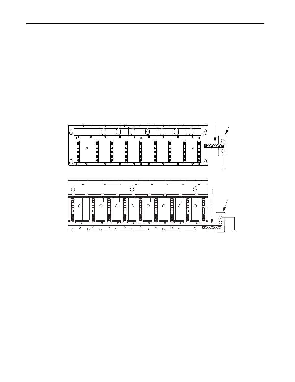
1. Disconnect the braided grounding strap from the grounding stud on the
right side of the power rail.
2. Loosen the mounting bolts (removing the bolts is not necessary).
3. Lift the power rail up and off of the mounting bolts.
TIP Because parameter settings reside in the Logix Designer application,
you do not need to perform any tuning or set-up procedures.
Braided Ground Strap
100 mm (3.9 in.)
Bonded Cabinet Ground
Power Rail
2094-PRx
Braided Ground Strap
100 mm (3.9 in.)
Bonded Cabinet Ground
Power Rail
2094-PRSx

Table of Contents

Other manuals for Allen-Bradley Kinetix 6000

Questions and Answers:

Question and Answer IconNeed help?

Do you have a question about the Allen-Bradley Kinetix 6000 and is the answer not in the manual?

Allen-Bradley Kinetix 6000 Specifications

General IconGeneral
Control TypeDigital
FeedbackResolver, Encoder
Protection RatingIP20
Power Range0.4…22 kW
CommunicationEthernet/IP
Ambient Temperature0°C to 50°C
AxisSingle-axis, Multi-axis
SafetySafe Torque-Off
Control ModesVelocity, Torque, Position
Relative Humidity5% to 95% (non-condensing)
Vibration Resistance5.9 m/s² (0.6 g) from 10 Hz to 500 Hz
Shock Resistance15 g, 11 ms
Storage Temperature-40°C to 70°C

Related product manuals