Rockwell Automation Publication 6000-UM002E-EN-P - April 2018 23
Drive System Layout Chapter 2
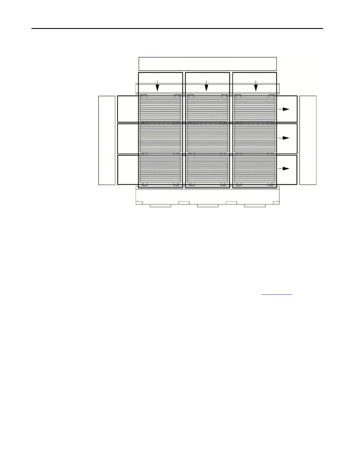
Figure 14 - Isolation Transformer Primary and Secondary Winding Orientation
The secondary windings are brought out to corresponding vertical isolated stand-
offs on the body of the transformer (orientated U, V, and W from left to right as
viewed from the front).
The U/W/V phase interconnections to the isolation transformer secondary
windings are all on the front of the isolation transformer. The power cable
connections to the power modules are made at the factory. Therefore, the field
power cable connections need to be made at the isolation transformer secondary
winding termination points, because the isolation transformer cabinet and power
module cabinet are shipped separately (see publication 6000-IN006
).
Isolation Transformer Temperature Monitor
A discrete transformer temperature monitor is mounted on the LV door in the
isolation transformer cabinet. There are two types of transformer temperature
monitors, and the type used depends on the drive rating. Three temperature
sensors are embedded in the isolation transformer. The monitor can be set to
indicate an alarm condition or a trip condition, dependent on the temperature
detected.
PRIMARY WINDING INPUT
SECONDARY WINDING OUTPUT
A (L1) B (L2) C (L3)
U
V
W
SECONDARY WINDING OUTPUT
U
V
W

 Loading...


