Rockwell Automation Publication 6000-UM002E-EN-P - April 2018 113
Preventative Maintenance and Component Replacement Chapter 5
Inspect UPS
1. Check there are no obstructions or dirt/debris in the exhaust heat fan.
2. Ensure there are no visible signs of damage.
Check UPS Output Voltage
1. Open the LV Control cabinet door.
2. Turn off the back-up control power circuit breaker (CB5) and the
customer-supplied power supply circuit breaker (CB1).
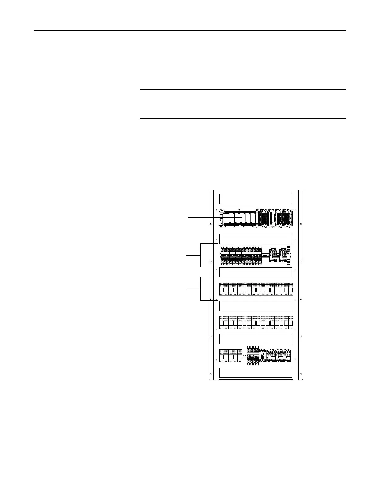
Figure 47 - Circuit Breaker Location in LV Control Cabinet
3. Press ON on the front of the UPS.
4. Using a voltmeter, check the output voltage of the UPS by checking the
input voltage on the line side of the CB2 circuit breaker (equivalent
electrical point).
The input voltage must be 110/120/220/240V AC optional.
If the drive has not been turned on for more than 3 months, the UPS batteries
must be charged for at least 10 hours. Apply either MV to the drive or
customer-supplied control power.
PLC
LV control relays
Circuit breakers

 Loading...


