30 Rockwell Automation Publication 6000-UM002E-EN-P - April 2018
Chapter 2 Drive System Layout
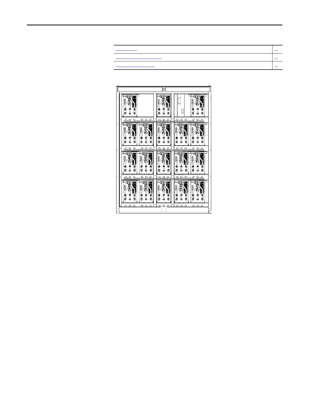
Power Module Cabinet
Figure 21 - Power Module Configuration
Power Modules
Power Modules are available in a wide variety of amperage ratings relating to the
required motor current. Power Modules rated up to and including 350 A are
fixed-mounted in the drive and ship already installed. Power Modules rated
above 350 A are shipped separately, therefore site installation and cable
connection is needed. In this case, a lifting cart is supplied for power cell
replacement.
An optional built-in Power Module bypass feature is also available for all drive
ratings. With the Power Module inside pass circuit, the drive can continue to run
without shutting down when encountering a Power Module failure. This ensures
a higher level of process reliability. Since the drive uses a solid-state bypass, the
dimensions of the drive does not increase when adding the automatic bypass
option.
Power Modules 30
Hall Effect Current Sensors (HECs) 33
Top-mounted Cooling Fan(s) 33

 Loading...


