Rockwell Automation Publication 6000-UM002E-EN-P - April 2018 105
Preventative Maintenance and Component Replacement Chapter 5
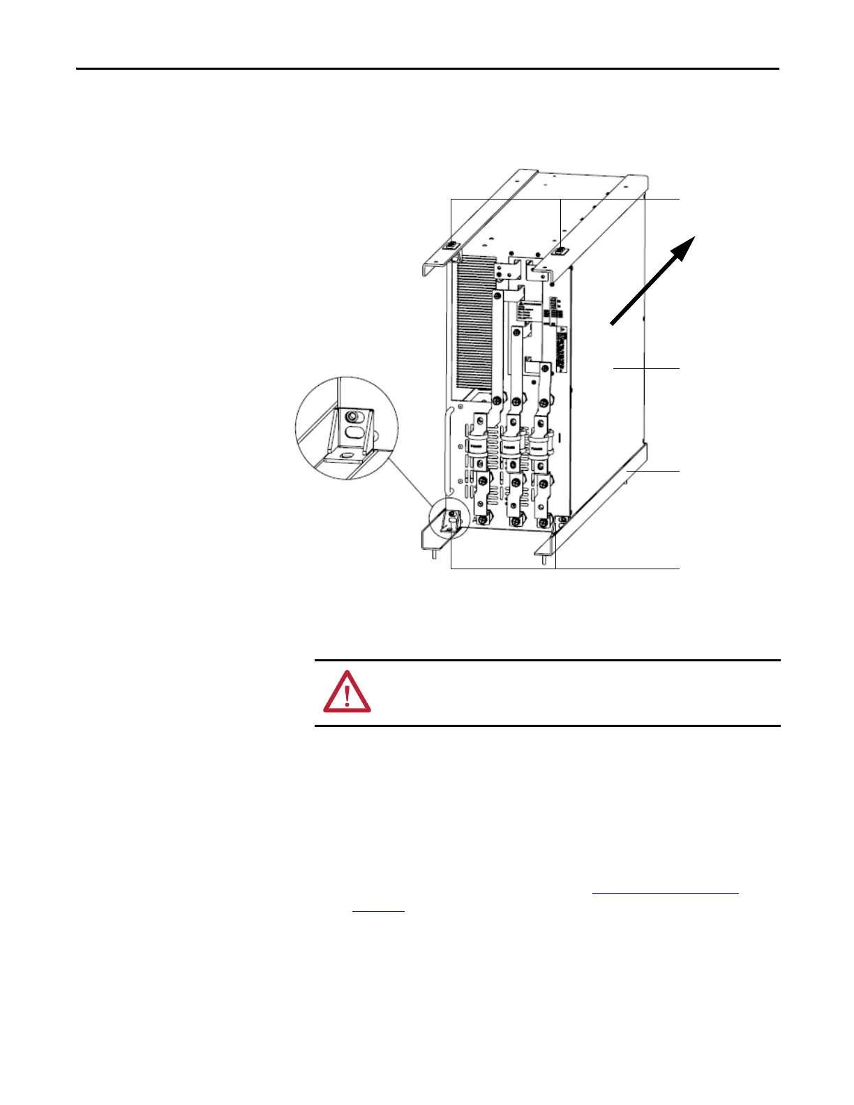
3. After installing the Power Module in place, use the mounting brackets and
the M6 × 16 large flat pad galvanized nickel screws to fix the four corners,
as shown below.
Replace Power Module Fuses
1. Remove the nut, lock washer, and washer from the top and bottom of the
fuse.
2. Remove the cables from the top and bottom of the fuse, and remove
another washer.
3. Install the new fuse, and replace cables and hardware in reverse order of
removal.
4. Torque all hardware to specifications (see Torque Requirements on
page 139).
Mounting brackets
Power Module
Guide rail
Mounting brackets
ATTENTION: Ensure the input circuit breaker feeding the drive is open. Lock out
and tagout the input circuit breaker before performing any work on the drive or
bypass units.
 Loading...


