34 Rockwell Automation Publication 6000-UM002E-EN-P - April 2018
Chapter 2 Drive System Layout
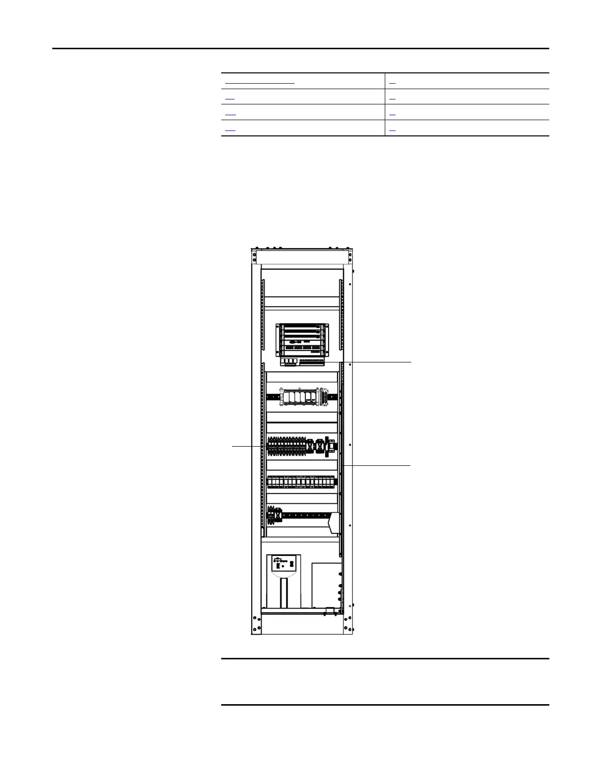
LV Control Cabinet
The LV Control cabinet consists of the Control Unit, the human-machine
Interface (HMI), PLC, AC/DC power supplies, contactors and relays.
The HMI is located on the front door of the LV Control cabinet, where an
operator can setup, monitor, and control the drive.
Figure 24 - LV Control Cabinet
Control Unit (all modules) 35
PLC 37
HMI 37
UPS 38
DTB1 terminal block strip
DTB2 terminal block strip
Phoenix connectors for
power wiring
When wiring a power supply to the Phoenix connectors, verify the
configuration on the markings and labels. Some power supplies may use two
6-pin connectors with similar configuration but have a different voltage input.

 Loading...


