Rockwell Automation Publication 6000-UM002E-EN-P - April 2018 37
Drive System Layout Chapter 2
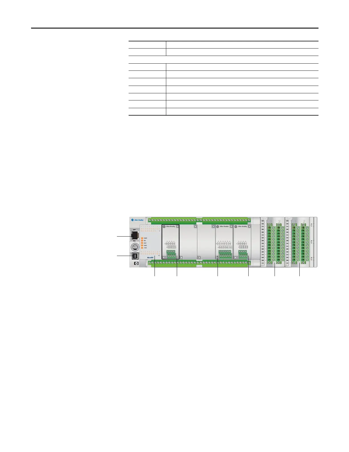
PLC
The PowerFlex 6000 uses a Micro850 PLC to perform many of its internal
control functions. The PLC controls and monitors the cooling fans, input and
bypass switching devices, door switch status, etc. The PLC is also responsible for
interfacing with the user's automation control system via many optional
communication protocols. Standard communication protocols are EtherNet/IP,
Modbus/TCP Server and Modbus RTU. Optional communication modules are
available to support other communication protocols.
Figure 27 - PLC Overview
HMI
The PowerFlex 6000 HMI is a PanelView™ Plus 6 series, catalog number 2711P-
T7C4D9.
The HMI is connected to the controller (Micro850) through a communication
interface (standard RJ45 EtherNet/IP connection). The HMI configures
operating parameters and input operation commands, and displays the operation
status, operation parameters, parameter trends, and fault messages.
5V 5V power supply indicator
3.3V 3.3V power supply indicator
Digital Signal Processor Board Indicator Lights
HVEN Allow High voltage switching on indicator
RUN Drive Running indicator
Fault Drive is in fault state
Trip Drive is in trip state; any fault can result in trip
Standby –
Standby –
Standby –
Power input
Extend I/O Extend I/OPlug inPLC Plug in Plug in
EtherNet/IP port

 Loading...


