98 Rockwell Automation Publication 6000-UM002E-EN-P - April 2018
Chapter 5 Preventative Maintenance and Component Replacement
Replace Voltage Sensing Board
1. Remove the Voltage Sensing Board input and output cables.
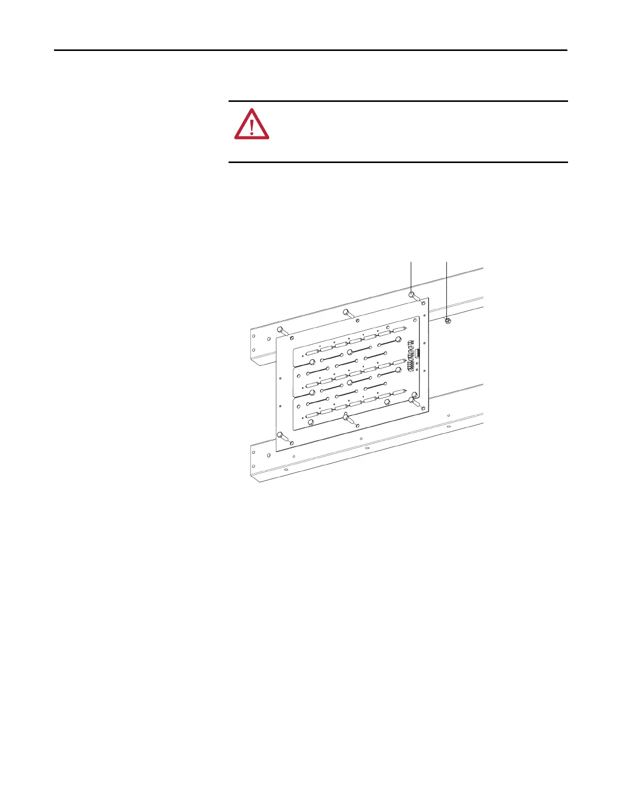
2. Remove the eight nylon nuts to remove the Insulation Board from the
cabinet side sheet.
Figure 31 - Remove the Insulation Board
3. Remove the nylon nuts which connect the Voltage Sensing Board to the
Insulation Board.
ATTENTION: To prevent electrical shock, disconnect the main power before
working on the Voltage Sensing Board. Verify that all circuits are voltage-free,
using a hot stick or appropriate high voltage-measuring device. Failure to do so
may result in injury or death.
Nylon M10 nut (6)Nylon M10 x 40 bolt (6)

 Loading...


