22 Rockwell Automation Publication 6000-UM002E-EN-P - April 2018
Chapter 2 Drive System Layout
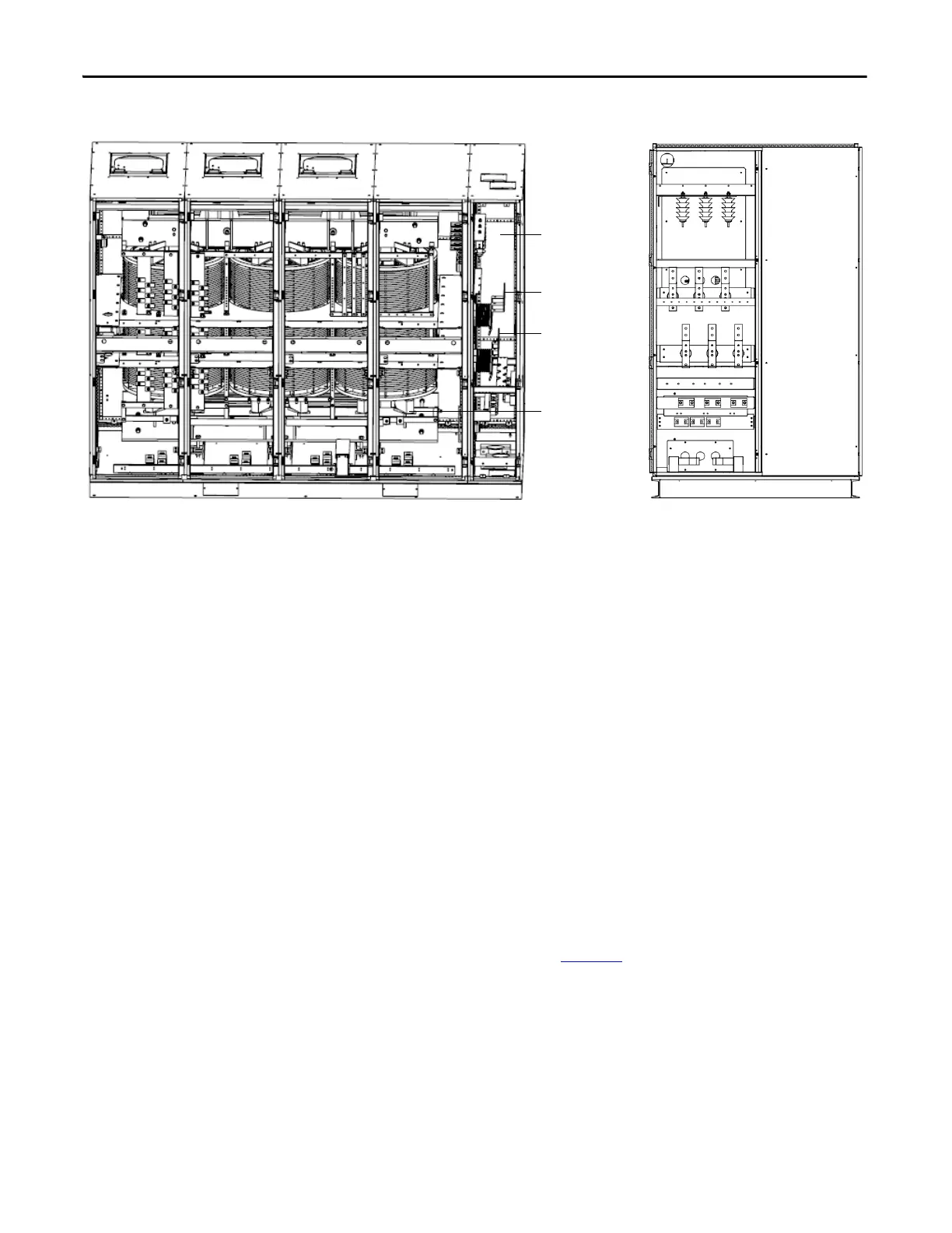
Figure 13 - Isolation Transformer Cabinet, Type C (Junction cabinet applied for cable connection)
Isolation Transformer
The primary winding of the isolation transformer is rated for the voltage of the
distribution system. It is connected to the distribution system by the incoming
line power cables. The secondary windings of the isolation transformer are
connected to the inputs of the power modules. The secondary low voltage
winding is to feed the low voltage power modules.
There are between 9 and 27 three-phase secondary side windings, dependent on
the motor voltage requirements from 2.3 kV to 11 kV. The phase relationship
between the secondary windings are optimized to provide the highest reduction
of line side harmonics.
The isolation transformer’s three-phase primary coils are oriented A, B, and C
from left to right, as viewed from the front. The secondary windings are also
divided into three principal sections from top to bottom. The upper third are to
feed the power modules in the U output phase. The middle third are to feed the
power modules in the V output phase. The bottom third are to feed the power
modules in the W output phase (Figure 14
).
L3 L1
WV U
L2
Junction
cabinet
Incoming line
power cable
connections
Outgoing motor
power cable
connections
Isolation
Transformer
Front View Side View

 Loading...


