Rockwell Automation Publication 6000-UM002E-EN-P - April 2018 35
Drive System Layout Chapter 2
Control Unit (all modules)
The control unit provides the core functionality of the variable frequency drive.
This includes controlling the power modules to produce the required output
voltage and frequency, monitoring the power modules, motor voltage, and motor
current to provide alarm and trip signals based on the information.
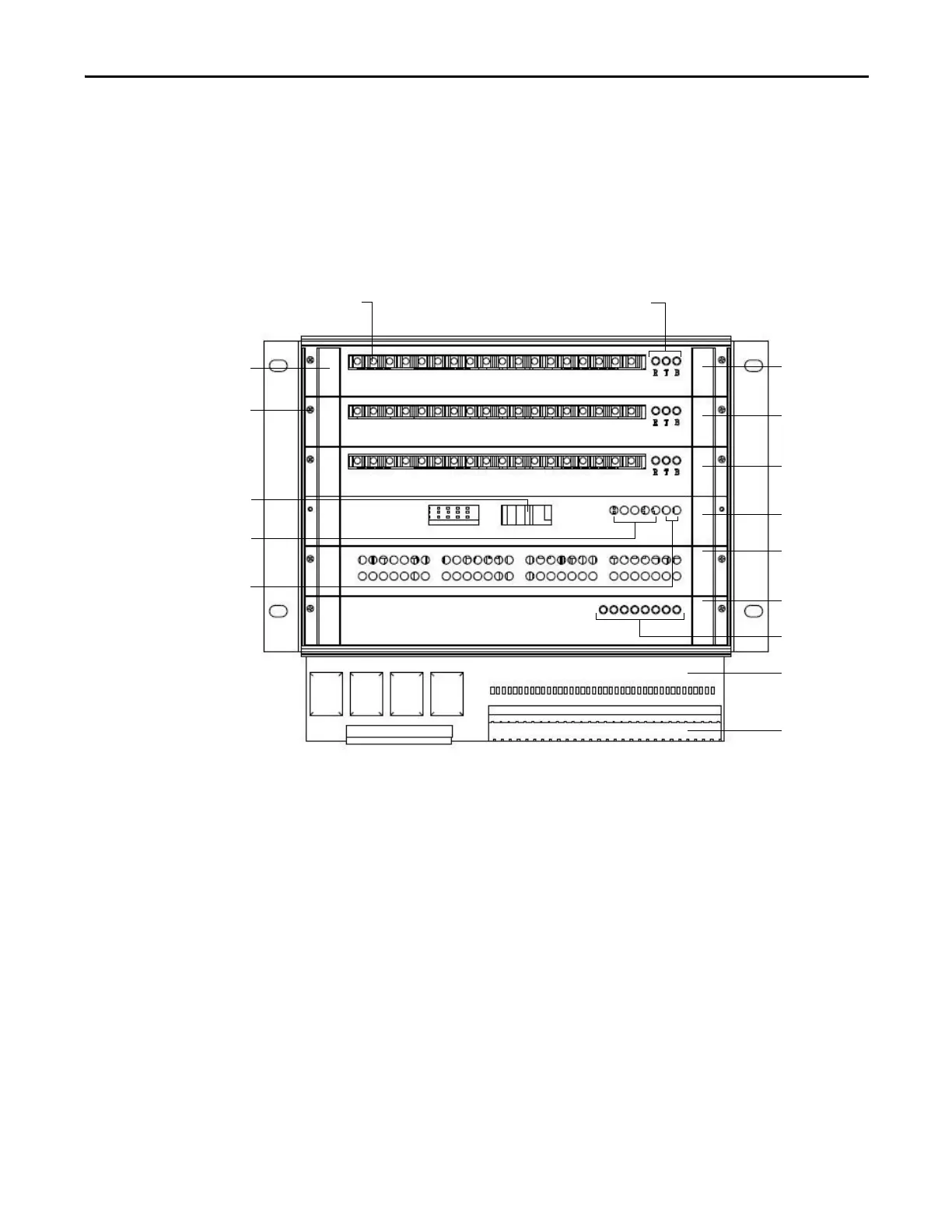
Figure 25 - PowerFlex 6000 Interface
The CPU Board accepts external inputs through the connected communication
network, hard-wired control devices or user interactions via the HMI to
determine the actions required of the drive. The CPU Board also monitors
motor voltage and current as well as internal inputs from the PLC, analog and
digital signal processor boards and Power Modules. It uses these inputs in its
motor control and protection algorithms to determine the necessary actions to
be taken and outputs to be set. In combination with the PWM Boards, the CPU
board sends the necessary optical PWM control signals to the Power Modules to
allow the Power Modules to output the required voltage and frequency to the
motor
Transceive r
indicators
PWM board A
PWM board B
PWM board C
CPU board
Analog signal
processor board
(AT)
Digital signal
processor board
(DT)
Status indicators
Interface
terminals
Fiber optic sockets
Board mounting
screw
PLC
communication
interface
Power indicators
DB board
Board handle
Status

 Loading...


