106 Rockwell Automation Publication 6000-UM002E-EN-P - April 2018
Chapter 5 Preventative Maintenance and Component Replacement
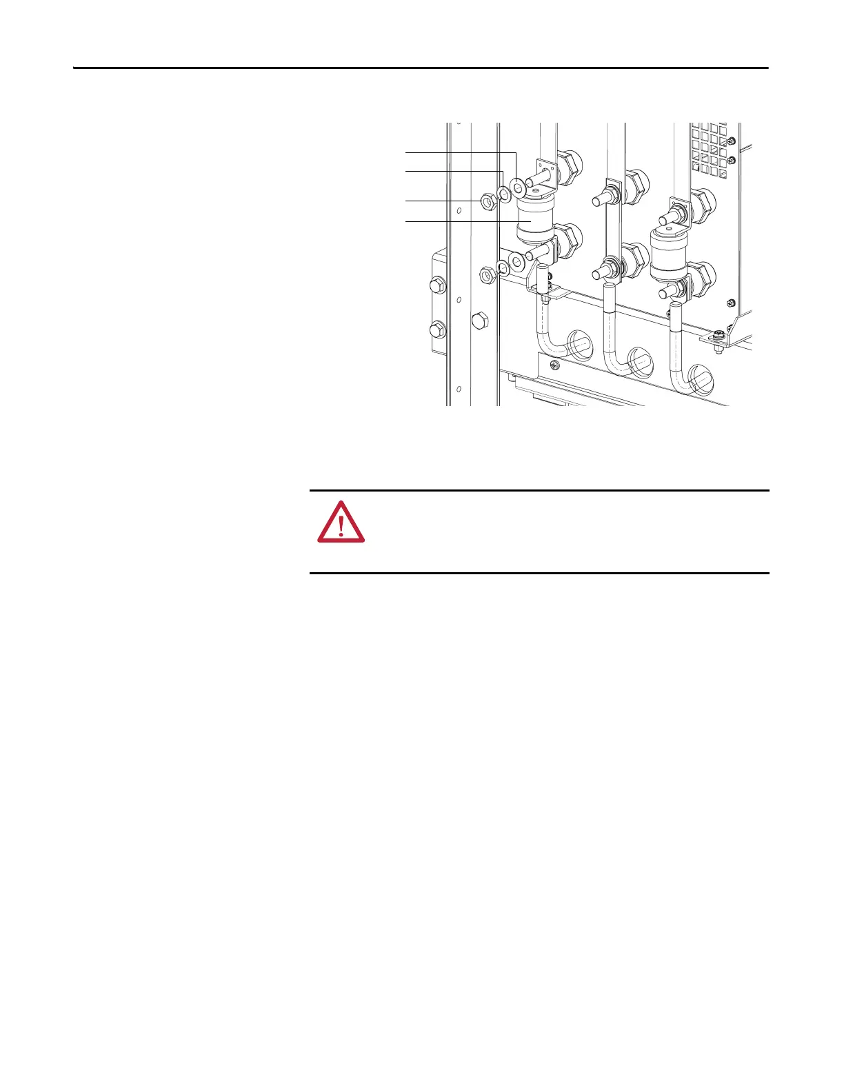
Figure 37 - Exploded View of Power Module Fuse
Inspect or Replace HECS
PowerFlex 6000 drives have two current sensors. For Power Module rating of
<200 A, they are located inside the Power Module cabinet. For Power Module
rating of 200...680 A, they are located inside the Transformer cabinet. Verify that
the current sensor wire connector is properly seated. Check for obvious signs of
damage.
1. Unplug the Current Sensor Connector from the HECS.
ATTENTION: To prevent electrical shock, disconnect the main power before
working on the drive. Verify that all circuits are voltage-free, using a hot stick or
appropriate high voltage-measuring device. Failure to do so may result in injury
or death.

 Loading...


