Rockwell Automation Publication 6000-UM002E-EN-P - April 2018 19
Chapter 2
Drive System Layout
All PowerFlex 6000 power modules designed as front connection. For a drive
amperage rating ≤350 A (304 A for heavy duty), a fixed-mounted power module
design is supplied. Fixed-mounted modules are shipped installed in the drive.
For a drive amperage rating of >350 A (304 A for heavy duty), power modules are
shipped separately, therefore site installation and cable connection is needed. In
this case, a lifting cart is supplied for power cell replacement.
The PowerFlex 6000 drive is shipped in two sections, the Isolation Transformer
cabinet and the Power Module/LV Control cabinet. See the PowerFlex 6000
Medium Voltage Variable Frequency Drive Shipping, Handling, and Installation
Instructions, publication 6000-IN006
.
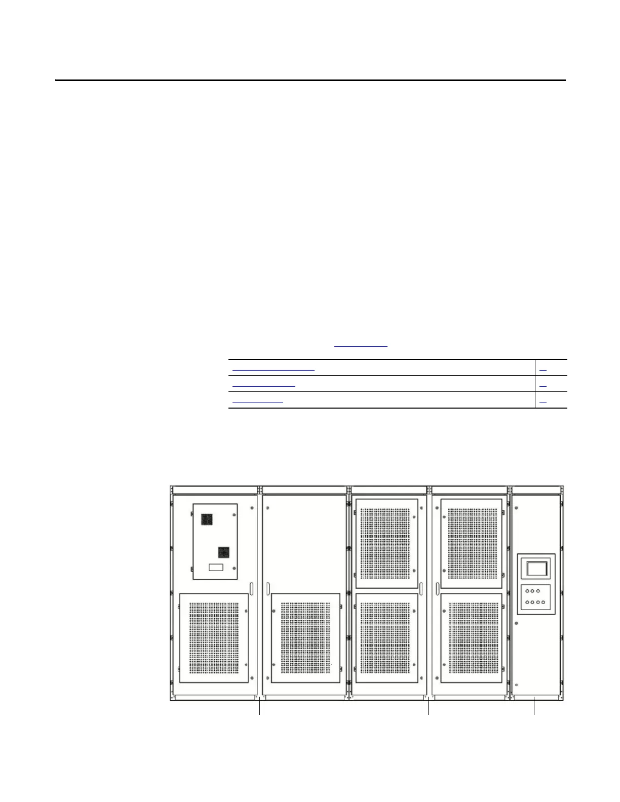
Elevation Drawings
Depending on the drive rating, the system layout may be different.
Figure 10 - Drive Configurations
Isolation Transformer Cabinet 20
Power Module Cabinet 30
LV Control Cabinet 34
Isolation Transformer cabinet Power Module cabinet LV Control
cabinet

 Loading...


