Publication 1747-RM001G-EN-P - November 2008
SLC Communication Instructions 12-31
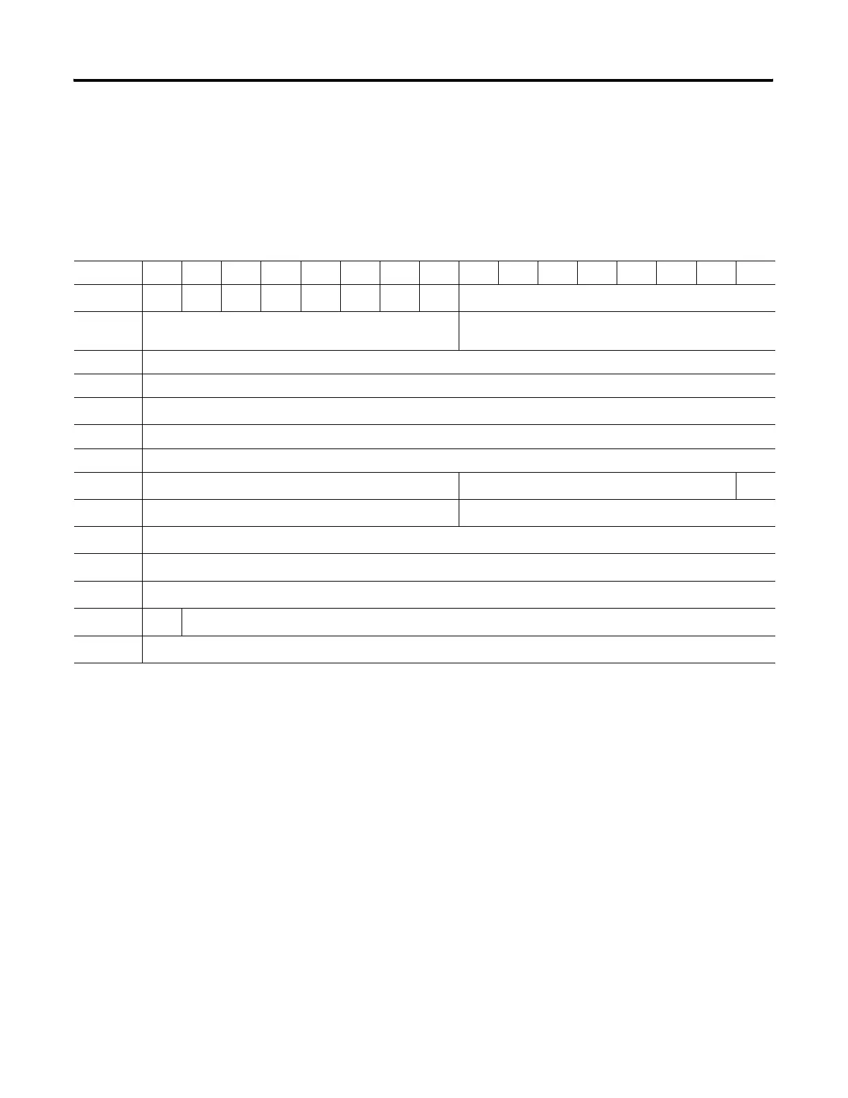
Control Block Layouts
The control block layout is shown below for 500CPU or PLC-5 controller as
the target device.
Table 12.11 Read or Write, Local or Remote
(1)
to a 500 CPU or PLC-5
(1)
(Without Logical ASCII/Symbolic Addressing)
15 14 13 12 11 10 09 08 07 06 05 04 03 02 01 0
Word 0 EN ST DN ER
CO
(1)
EW NR TO Error Code
Word 1 Reserved Target Node Address (Local)/Remote Station Address
(Remote)
Word 2 Number of Elements
Word 3 File Number
Word 4
File Type (S, B, T, C, R, N) (O, I, F, ST, A)
(1)
Word 5 Element Number
Word 6 Not Used
Word 7
(1)
Remote Bridge Address (Remote only) Reserved (Internal Messaging Bits) WQ
Word 8
(1)
Reserved (Internal Messaging Bits) Message Timer Preset
Word 9
(1)
Message Timer Scaled Zero
Word 10
(1)
Message Timer Accumulator
Word 11
(1)
Reserved (Internal Messaging Bits)
Word 12
(1)
AO=0 Reserved (Internal Messaging Bits)
Word 13
(1)
Reserved (Internal Messaging Bits)
(1)
SLC 5/03 and higher processors only.

 Loading...


