Publication 1747-RM001G-EN-P - November 2008
Application Example Programs G-23
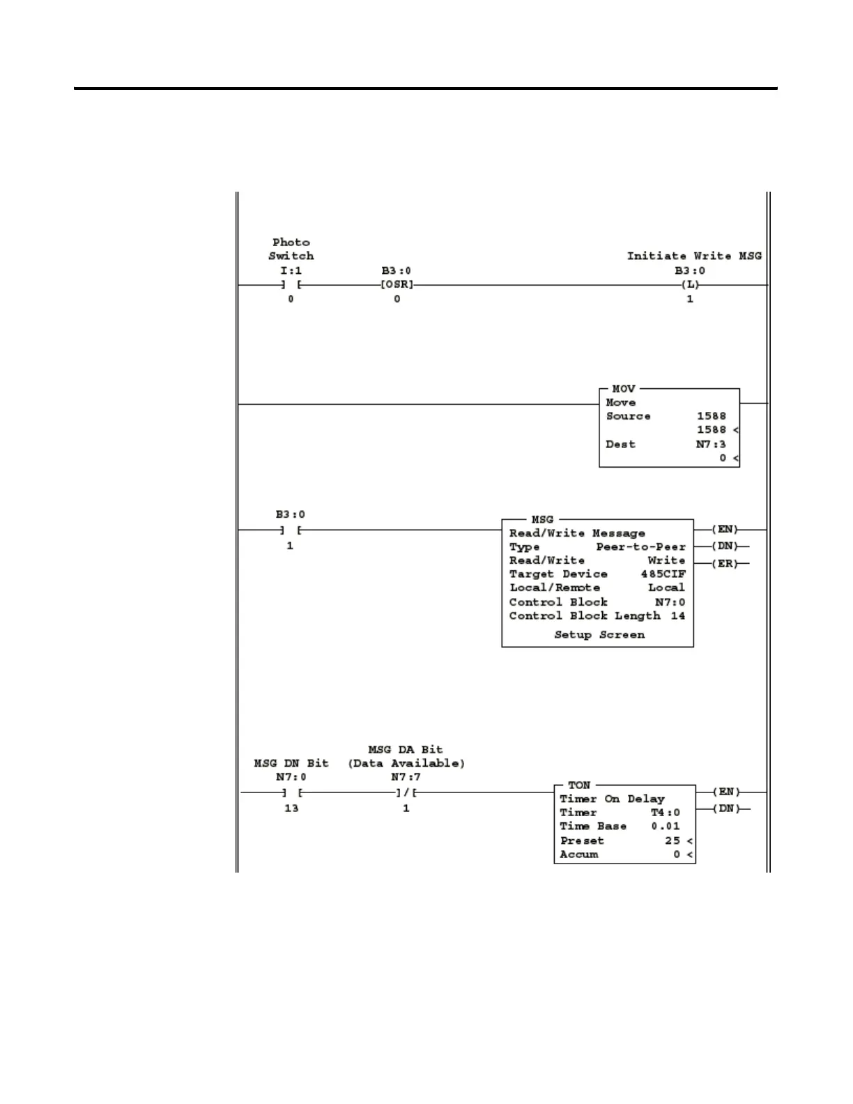
Example Ladder Program
This rung detects the Photo Switch input going from
false-to-true, and latches internal storage bit B3/1.
This rung moves the decimal value for the bar code decoder “trigger”
command into the MSG instructions “Offset” parameter. The programming
software does not allow values greater than 255 decimal to be entered into a
MSG control block “Offset” value.
The internal storage bit (B3/1) gives the MSG instruction a false-to-true
transition to send the initial command. B3/1 remains latched until both the
DN and DA bits are set for the MSG instruction.
The initial reply from an Enhanced Bar Code Decoder will result in MSG DN = 1 and MSG DA = 0.
This simply indicates that the decoder has received the command, but has not yet formulated a
reply. The maximum time delay needed between sending the initial command and sending a poll
to get the reply is 250 ms. In most cases this delay could be much less (30 ms to 100 ms),
depending on the number of features the decoder is configured for.

 Loading...


