118 Rockwell Automation Publication 1783-UM007G-EN-P - February 2017
Chapter 4 Install Stratix 5410 Switches
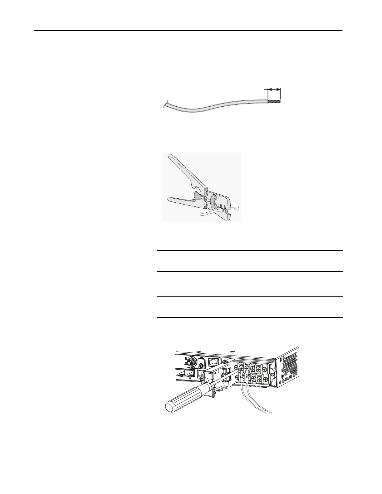
5. Strip each of the two wires to 6.3 mm (0.25 in.) ± 0.5 mm (0.02 in.).
Do not strip more than 6.8 mm (0.27 in.) of insulation from the wire.
Stripping more than the recommended amount of wire can leave
exposed wire from the connector after installation.
6. Insert the wire into a spade terminal, and crimp it to the wire.
You can also use a ring or flanged spade terminal.
7. Loosen the terminal screw, and slide the terminal under the screw and
washer.
8. Make the power connection:
• For AC power, connect the line wire into the terminal screw that is
labeled L and the neutral wire into the terminal screw labeled N.
IMPORTANT Use the appropriate terminal screws that are based on power supply
type: high-voltage (AC or DC) or a low-voltage (DC).
IMPORTANT Make sure that you cannot see any wire lead. Only wire with
insulation should extend from the terminal screw.
6.3 mm (0.25 in.) ± 0.5 mm (0.02 in.)
32562-M

 Loading...


