Rockwell Automation Publication 1783-UM007G-EN-P - February 2017 119
Install Stratix 5410 Switches Chapter 4
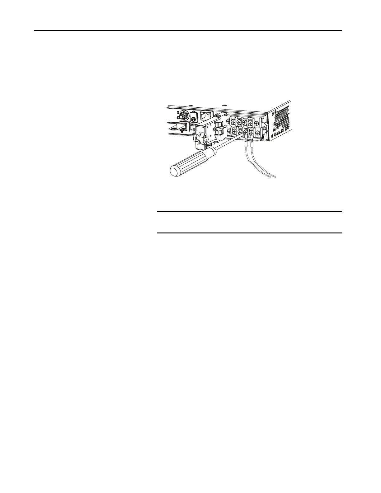
• For DC power, connect the positive wire into the terminal screw that
is labeled +, and the negative wire into the terminal screw labeled -.
For low-voltage DC power, connect the wires to the terminals labeled
Lo.
For high-voltage DC power, connect the wires to the terminals
labeled Hi.
9. Torque the captive screws above the wires to 0.79 N•m (7 lb•in).
10. Complete the power connection:
• For AC power, connect the other end of the line wire (the one
connected to L) to the line terminal on the AC power source.
Connect the other end of the neutral wire (the one connected to N)
to the neutral terminal on the AC power source.
• For DC power, connect the other end of the positive wire (the one
connected to +) to the positive terminal on the DC power source.
Connect the other end of the negative wire (the one connected to –)
to the negative terminal on the DC power source.
11. Close the power input terminal cover.
12. Use a ratcheting torque screwdriver to torque the screw to 0.79 N•m
(7 lb•in).
13. Turn on the power at the AC or DC circuit.
14. Verify that the PSU 1 or 2 status indicator on the switch and PSU OK
status indicator on the power supply module are green.
IMPORTANT Make sure that you cannot see any wire lead. Only wire with
insulation should extend from the terminal screw.
32563-M

 Loading...


