76 Rockwell Automation Publication 1783-UM003G-EN-P - December 2012
Chapter 3 Manage the Switch via the Device Manager Web Interface
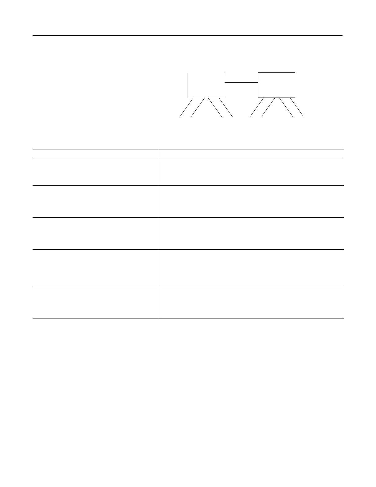
The following figure and chart illustrate DHCP persistence behavior.
FA1
FA2
FA3
FA7
FA4
FA5
FA6
FA8
Switch 1
Switch 2
DHCP Persistence Behavior
If Then
• Switch 1 has ports FA1…FA3 in its persistence table
• Switch 2 has ports FA4, FA5, FA6 and FA8 in its
persistence table
• Reserve Only is not selected and DHCP snooping is off
A new device connected to switch 1 FA1 receives an IP address from the Switch 1
persistence table. A broadcast request is also sent across the network. Switch 2 will
respond if there is an unassigned address in its pool. This may override the assignment
made by switch 1.
• Switch 1 has ports FA1…FA3 in its persistence table
• Switch 2 has ports FA4, FA5, FA6 and FA8 in its
persistence table
• Reserve Only is selected in both switches and DHCP
snooping is off
A new device connected to switch 1 FA1 receives an IP address from the switch 1
persistence table. A broadcast request is also sent across the network. Switch 2 will not
respond to the request. Note that if the device is connected to FA7 of switch 1, it will not
receive an IP address from the switch pool because it is not defined in the persistence
table, and unused addresses in the pool are blocked.
• Switch 1 has ports FA1…FA3 in its persistence table
• Switch 2 has ports FA4, FA5, FA6 and FA8 in its
persistence table
• Reserve Only is selected in switch 1 and DHCP snooping
is off, but not switch 2 when DHCP snooping is off
A new device is connected to FA1 receives an IP address from the persistence table. A
broadcast request is also sent across the network. Switch 2 will not respond to the request.
In addition, a device connected to FA4 receives an IP address from the switch 2 persistence
table. A broadcast request is sent out, and switch 1 responds with an unused IP address
from its pool.This may override the assigned port.
• Switch 1 has ports FA1…FA3 in its persistence table
• Switch 2 has ports FA4, FA5, FA6 and FA8 in its
persistence table
• DHCP Snooping is selected
• Reserved only is selected
A new device connected to switch 1 FA1 receives an IP address from the Switch 1
persistence table. A broadcast request is not sent across the network, therefore Switch 2
will not respond. Note that if a device is connected to FA7 (not defined in the DHCP
persistence table) of Switch 1, it will not receive an IP address from the switch pool
because it is not defined in the persistence table, and unused addresses in the pool are
blocked.
• Switch 1 has ports FA1…FA3 in its persistence table
• Switch 2 has ports FA4, FA5, FA6 and FA8 in its
persistence table
• DHCP Snooping is selected
• Reserved only is not selected
A new device connected to switch 1 FA1 receives an IP address from the Switch 1
persistence table. A broadcast request is not sent across the network, therefore Switch 2
will not respond. Note that if a device is connected to FA7 (not defined in the DHCP
persistence table) of Switch 1, it will receive an unassigned IP address from the Switch 1
pool.
 Loading...


