Copyright © 1996 General Motors Corp. 6–9
REBUILD OF SUBASSEMBLIES
clutch trimmer valve 21; and springs 31 and 32 (if
present), stop 33, plug 30, and fourth clutch trimmer
valve 29. For models that do not have spring 32, dis-
card spring 31 and install new springs 31 and 32.
(8) If present, remove accumulator valve 28,
spring 27, and stop 26.
NOTE:
•
For AT 545 models, S/N 3210418516 through
3210419140 only, proceed with Step (9).
•
For all other models, skip Step (9) and proceed
with NOTE preceding Step (10).
(9) For AT 545 models S/N 321041856
through 3210419140 only, check the etched part num-
ber on trimmer valves 12, 16, 21, and 29. Replace any
incorrect P/N 23016686 trimmer valves at reassembly
with the correct P/N 23014097 trimmer valves.
NOTE:
Valve stop 39 and spacer 42 are spring-loaded and
must be restrained while retainer pins 36 are being
removed. (Valve stop 39 replaces two parts used in
earlier models.)
(10) Remove one retainer pin 36 from control
valve body 11. Remove spacer 42, spring 41, and 1–2
relay valve 40.
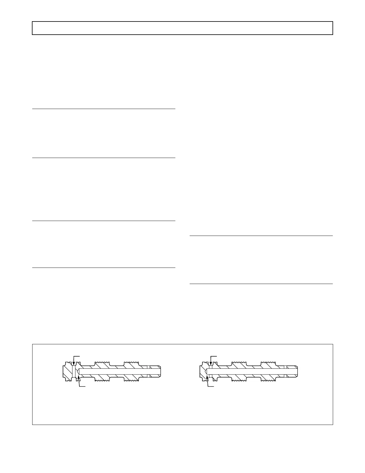
(11) Examine the interior bore of 1–2 relay
valve 40. If the configuration of the valve matches
View
A
, Figure 6–19, discard the valve and replace it
with a new valve at reassembly.
(12) Remove the other retainer pin 36 from
control valve body 11. Remove stop 39, spring 38, and
2–3 relay valve 37.
(13) Compress adjusting ring 51 and remove
retainer pin 52. Remove adjusting ring 51, washer 50,
plug 49 (if present), valve stop 48, valve spring 47, and
hold regulator valve 46 from the bore in control valve
body 11.
(14) Compress adjusting ring 58 and remove
retainer pin 59. Remove adjusting ring 58, stop 57,
spring 56 (if present), 1–2 modulator valve 55, 1–2
shift signal valve 54, and spring 83 (if present).
(15) Compress adjusting ring 64 and remove
retainer pin 65. Remove adjusting ring 64, stop 63,
spring 62, 2–3 modulator valve 61, and 2–3 shift sig-
nal valve 60.
NOTE:
Some units may have been field modified to prevent
the 3–4 shift. Take note of the position of retainer
pin 71 and stop 69; install parts in the same position
as removed.
(16) Compress adjusting ring 70 and remove
retainer pin 71. Remove adjusting ring 70, stop 69,
spring 68, 3–4 modulator valve 67, and 3–4 shift sig-
nal valve 66.
Figure 6–19. 1–2 Relay Valve
Insufficient Bore Depth Drilling
VIEW A
RELAY VALVE
INCORRECT DRILLING, DOES NOT
INTERSECT 0.125 in. (3.18 mm)
EXHAUST PORT
VIEW B
CORRECTLY DRILLED VALVE, DOES
INTERSECT 0.125 in. (3.18 mm)
EXHAUST PORT
0.125 in. (3.18 mm) EXHAUST PORT
Correct Bore Depth Drilling
0.125 in. (3.18 mm) EXHAUST PORT
V03135
 Loading...


