2–14 Copyright © 1996 General Motors Corp.
AT 500, 1500 SERIES AUTOMATIC TRANSMISSIONS
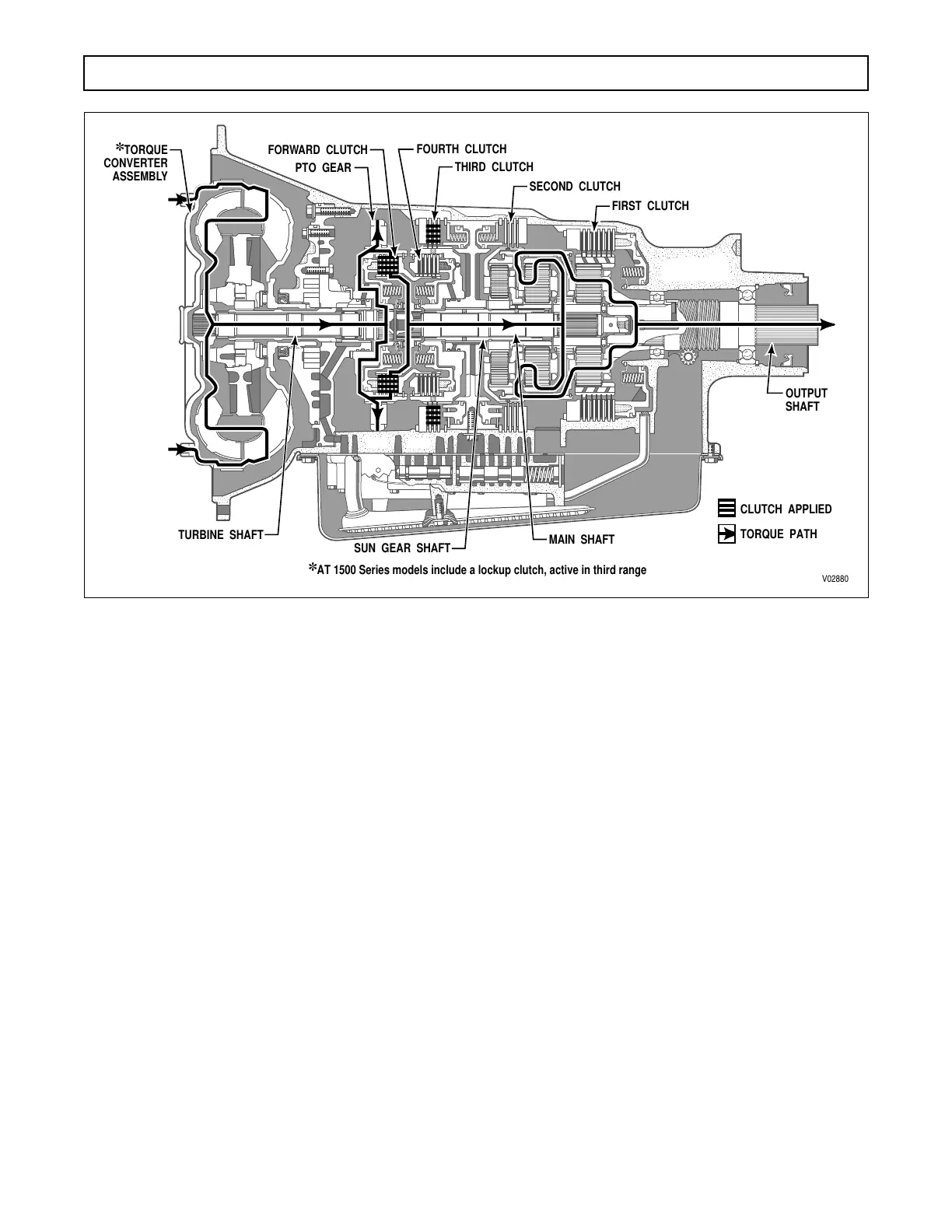
e. Third-Range Operation
(Figure 2–4)
. The
forward and the third clutches are applied. The third
clutch application anchors the sun gear shaft against
rotation, which, in turn, prevents the center sun gear
(splined to rear of shaft) from rotating. The forward
clutch application locks the turbine shaft and main
shaft together, to rotate as a unit. The rear sun gear is
splined to both the main shaft and the center ring gear
and rotates at turbine speed. With the center sun gear
stationary and the center ring gear rotating, the ring
gear drives the center planetary carrier pinions. This
carrier (and also the rear planetary carrier) is splined to
the planetary connecting drum and rotates with it as a
unit. The rear carrier is splined to the transmission out-
put shaft which produces an output ratio of 1.41:1.
f. Converter Operation
(AT 1500 Series Mod-
els).
During converter operation, 3–4 clutch feed
pressure is exhausted, allowing the lockup valve to
remain in the downward (unapplied) position. Main
overage flow is routed through the lockup valve to
the space between the turbine and stator shafts. From
there, fluid passes through slots in the turbine hub to
an area between the torque converter cover and pis-
ton. Converter-in pressure moves the piston away
from the reaction surface and provides the fluid nec-
essary for proper filling of the torque converter ele-
ments. Fluid exhausts through slots in the stator and
is sent to the cooler circuit.
g. Lockup Operation
(AT 1500 Series Models).
After the 2–3 upshift has occurred, main pressure be-
gins to shift the lockup valve upward. As the lockup
shift is made, three simultaneous changes occur: con-
verter-in pressure is exhausted, eliminating the sepa-
rating force between the converter cover and piston;
main overage is routed directly to the cooler circuit;
and 3–4 clutch feed pressure is directed to the torque
converter creating a pressure differential across the
lockup piston. As a result, 3–4 clutch feed pressure ap-
plies the lockup clutch, providing increased operating
efficiency.
Figure 2–4. Third Range Power Flow
;;;;;;;;;;;;;;;;
;;;;;;;;;;;;;;;;
;;;;;;;;;;;;;;;;
;;;;;;;;;;;;;;;;
;;;;;;;;;;;;;;;;
;;;;;;;;;
;;;;;;;;;
;;;;;;;;;
;;;;;;;;;
V02880
TURBINE SHAFT
SUN GEAR SHAFT
PTO GEAR
FORWARD CLUTCH
THIRD CLUTCH
SECOND CLUTCH
FIRST CLUTCH
FOURTH CLUTCH
✽
TORQUE
CONVERTER
ASSEMBLY
MAIN SHAFT
TORQUE PATH
✽
AT 1500 Series models include a lockup clutch, active in third range
CLUTCH APPLIED
OUTPUT
SHAFT
 Loading...


