6–18 Copyright © 1996 General Motors Corp.
AT 500, 1500 SERIES AUTOMATIC TRANSMISSIONS
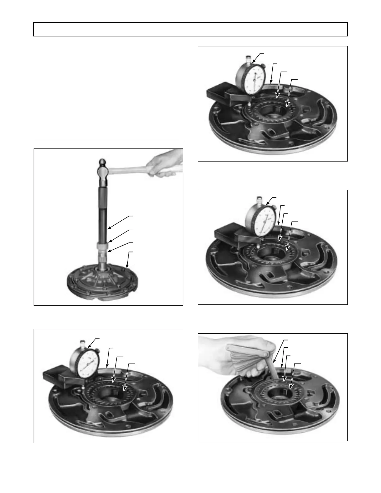
(5) Check the driven gear diametrical clear-
ance with a feeler gauge as shown in Figure 6–31. Re-
place the gear if the clearance is not within 0.0055–
0.0085 inch (0.14–0.22 mm) on a new gear or
0.0055–0.0089 inch (0.14–0.23 mm) on a used gear.
d. Assembly (Foldout 7,B)
NOTE:
• For models without lockup, proceed with Step (1).
• For models with lockup, skip Steps (1) and (2)
and proceed with Step (3).
Figure 6–27. Installing Stator Shaft Front Bushing
(AT 500 Series Models)
Figure 6–28. Zero Dial Indicator on Oil Pump
Body Surface
Figure 6–29. Dial Indicator Check of Oil Pump Driven
Gear End Clearance
Figure 6–30. Dial Indicator Check of Oil Pump Drive
Gear End Clearance
Figure 6–31. Checking Diametrical Clearance
of Oil Pump Driven Gear
H02934
PUMP BODY
STATOR SHAFT
J 23614-A
J 8092
H02935
OIL PUMP DRIVE
GEAR
OIL PUMP DRIVEN GEAR
OIL PUMP BODY
DIAL INDICATOR J 26857
H02936
OIL PUMP DRIVE
GEAR
OIL PUMP DRIVEN GEAR
OIL PUMP BODY
DIAL INDICATOR J 26857
H02937
OIL PUMP DRIVE
GEAR
OIL PUMP DRIVEN GEAR
OIL PUMP BODY
DIAL INDICATOR J 26857
H02938
OIL PUMP DRIVE
GEAR
OIL PUMP DRIVEN GEAR
OIL PUMP BODY
FEELER GAUGE
 Loading...


