Copyright © 1996 General Motors Corp. 5–1
5–1. SCOPE
This section covers disassembly of the transmission
into subassemblies.
5–2. GENERAL INFORMATION
a. General Information.
Refer to Sections 4
and 8 for general information as follows:
b. Removal of Exterior Hoses and Lines.
Re-
move hoses 1 and 4 (Foldout 13) and adapters as re-
quired, and any other exterior vehicle components at-
tached to the transmission.
5–3. TRANSMISSION DISASSEMBLY
a. Mounting of Transmission in
Table-Mounted Holding Fixture
NOTE:
•
For retarder-equipped models, proceed with
Step (1).
•
For models without retarder, skip Steps (1)
through (5) and proceed with Step (6).
(1) Remove four bolts 36 (Foldout 13) and
remove retarder control valve body assembly 18 and
transfer plate assembly 6 as an assembly.
(2) Remove gasket 1 and two jumper tubes 2.
(3) Remove four bolts 4 and flat washers 5
from the transfer plate assembly. Lift transfer plate
assembly 6 from retarder control valve body assem-
bly 18.
(4) Remove gasket 16, separator plate 17,
and a second gasket 16.
(5) Refer to Paragraph 6–7 for rebuild of the
retarder control valve body assembly. Refer to Para-
graph 6–8 for rebuild of the transfer plate assembly.
Skip Step (6) and proceed with Step (7).
(6) Remove PTO or six bolts 3 (Foldout
12,A), PTO cover 2, and gasket 1.
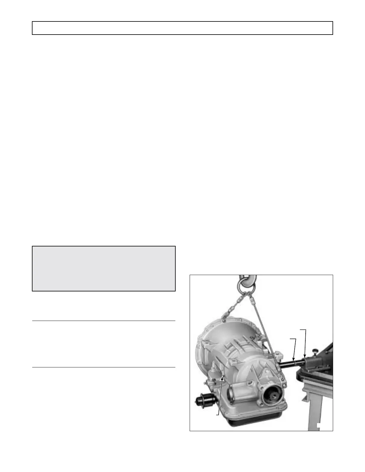
(7) Mount holding fixture J 23642-01 (Fig-
ure 5–1) onto PTO mounting pad.
(8) Install fixture base J 3289-20 onto work
table.
(9) Using hoist as shown in Figure 5–1, lift
transmission and holding fixture so that holding fixture
J 23642-01 can be installed into fixture base J 3289-
20. (Or, mount the transmission in a suitable turnover
stand.)
(10) Secure fixture in fixture base and posi-
tion the transmission with the torque converter upward
(Figure 5–2).
Figure 5–1. Transmission in Holding Fixture
Paragraph Title
3–16 Replacement of Components While
Transmission is in the Vehicle Chassis
4–2 Tools and Equipment
4–3 Replacement Parts
4–4 Careful Handling
4–5 Cleaning and Inspection
8–1 Wear Limits Data
CAUTION:
The torque converter must be held into the trans-
mission by a retaining device as shown in Figures
1–1 and 1–3. Be sure the retainer is in place be-
fore lifting the transmission.
H02892
J 23642-01
J 3289-20
LIFTING
LUG
Section 5 – DISASSEMBLY OF TRANSMISSION
 Loading...


