Copyright © 1996 General Motors Corp. 6–17
REBUILD OF SUBASSEMBLIES
(5) Coat the OD of a new non-prebored re-
placement bushing 18 (Foldout 7,B) with Loctite
®
601
sleeve retainer, or equivalent. Install bushing 18 into
the stator shaft with J 23614-A to a depth of flush to
0.005 inch (0.127 mm) below the end of the shaft (Fig-
ure 6–27). Remove any excess Loctite
®
from the shaft
housing.
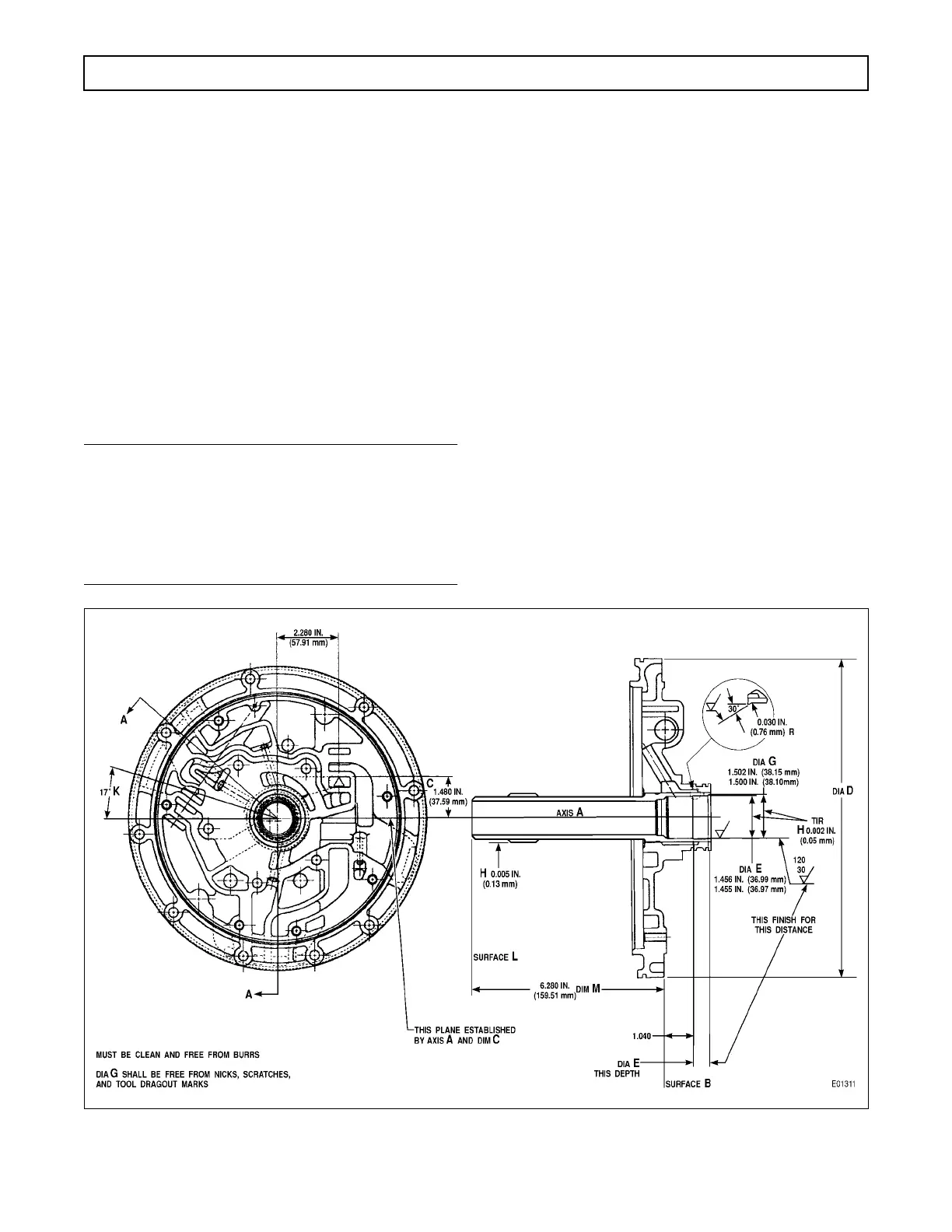
(6) Machine the bushing to the diameter and
microfinish specified (Figure 6–25) while maintaining
TIR not to exceed 0.003 inch (0.076 mm).
(7) Thoroughly clean the assembly of any
metal chips and dirt, being careful to clean all pas-
sages in the front support.
c. Pump Gear Clearance Check (Foldout 7,B)
NOTE:
Proper end play and side clearance of the oil pump
gears must be established before the pump is assem-
bled. Remove all nicks and burrs from the pump
and gear surfaces to facilitate accurate dial indica-
tor readings.
(1) Position oil pump body assembly 6, flat
side upward. Install drive gear 10 into pump body as-
sembly 6, so the internal tangs of the gear are facing
upward. Install gear 9 into the pump body 6 so that
the side of gear 9 marked with a diamond is down-
ward.
(2) Position dial indicator J 26857 on the
pump body as shown in Figure 6–28. Zero the dial while
the stylus (plunger) is contacting the pump body face.
(3) Without disturbing the dial setting, slide
the indicator to the driven gear (Figure 6–29). While
holding the indicator in position, record the reading. If
the clearance is not within 0.0008–0.0022 inch
(0.020–0.056 mm) on a new gear or 0.0008–0.0026
inch (0.020–0.066 mm) on a used gear, replace the
gear and repeat Steps (2) and (3).
(4) Slide the indicator to the drive gear (Fig-
ure 6–30). While holding the indicator in position,
record the reading. If the clearance is not within
0.0008–0.0022 inch (0.020–0.056 mm) on a new gear
or 0.0008–0.0026 inch (0.020–0.066 mm) on a used
gear, replace the gear and repeat Steps (2) and (4).
Figure 6–26. Installation of Stator Shaft (AT 1500 Series)
 Loading...


