6–28 Copyright © 1996 General Motors Corp.
AT 500, 1500 SERIES AUTOMATIC TRANSMISSIONS
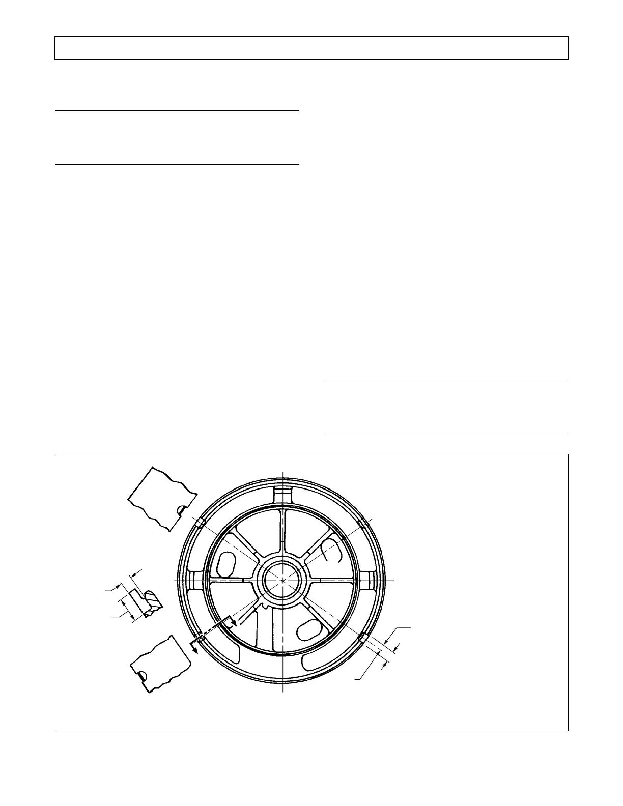
b. Rework of Center Support Piston Retainer
Locating Notches (Foldout 9,B)
NOTE:
Do not attempt this rework procedure unless ade-
quate machining capabilities are available.
If the notch broke away to let the retainer ride upward,
rework as shown in Figure 6–47.
c. Assembly (Foldout 9,B)
(1) Place center support 15 in a press, seal-
ring grooves side upward. To ensure proper alignment
of the oil hole in bushing 14 with the notch in support
15, the identifying notch of the bushing must lie in the
area indicated (Figure 6–48). Using bushing tool
J 24778 (for models without lockup) or J 39735 (for
models with lockup), install bushing 14 (Foldout 9,B)
as shown in Figure 6–49.
(2) If a special bushing tool is not available,
press bushing 14 flush to 0.010 inch (0.25 mm) below
the surface adjacent to the bore. The bushing must
withstand 500 pounds (2224 N) of end load as speci-
fied in the direction of Arrow A in Figure 6–48 after
assembly.
(3) Place piston 9 (Foldout 9,B) in its bore
without the piston sealrings in place, with the four
ejector pin bosses upward. Install piston return springs
8 in the twelve holes in third clutch piston 9.
(4) Place spring retainer 7 on piston 9, align-
ing the four holes in the piston. Using tool J 24453, in-
stall four new self-locking retainer washers 6 onto the
eight ejector pin bosses (Figure 6–50).
(5) Remove piston 9 from the support as-
sembly.
(6) Repeat steps (3) through (5) for piston 18.
(7) Install sealrings 10 and 17 into the inside
diameter groove of pistons 9 and 18. Install sealrings 11
and 16 into the outside diameter grooves of pistons 9
and 18. Be sure the lips of the sealrings and the flat side
of the piston face the same direction. Special care is re-
quired to prevent distortion, cutting, or stretching of the
sealrings. Apply oil-soluble grease to the sealrings.
(8) Install two hook-type sealrings 12 onto
the hub of center support 15.
NOTE:
Do not install the piston assemblies until the second
clutch stack check is made (Paragraph 6–17e).
Figure 6–47. Rework of Center Support Piston Retainer Locating Notches
E
E
L02953
SECTION E-E
(4 x Size)
0.110 in.
(2.79 mm)
0.320 in.
(8.13 mm)
0.200 in.
(5.08 mm)
Notches must be located
180 degrees from the original
location in order for the piston
to seat correctly.
IMPORTANT:
0.400 in.
(10.16 mm)
4 Slots
(2 each side
as shown)
 Loading...


