Copyright © 1996 General Motors Corp. 6–33
REBUILD OF SUBASSEMBLIES
(5) Inspect governor support pin 12 for evi-
dence of wear. If any wear is noted on the end or on
the OD of the pin, remove the pin using pin remover
tool J 28708 (Figure 6–57).
(6) Inspect test plugs 8 and 13 (Foldout
12,A). Replace if damaged.
(7) If it is necessary to replace a damaged
nameplate 5, remove one drive screw 4.
NOTE:
For accurate ordering of replacement parts, the in-
formation on the new nameplate must be identical
to the information that was stamped on the dam-
aged nameplate.
b. Assembly
(1) If snapring 9 (Foldout 12,A) was removed,
install a new snapring. Be sure to inspect the bore into
which bearing 4 (Foldout 12,B) fits for damage.
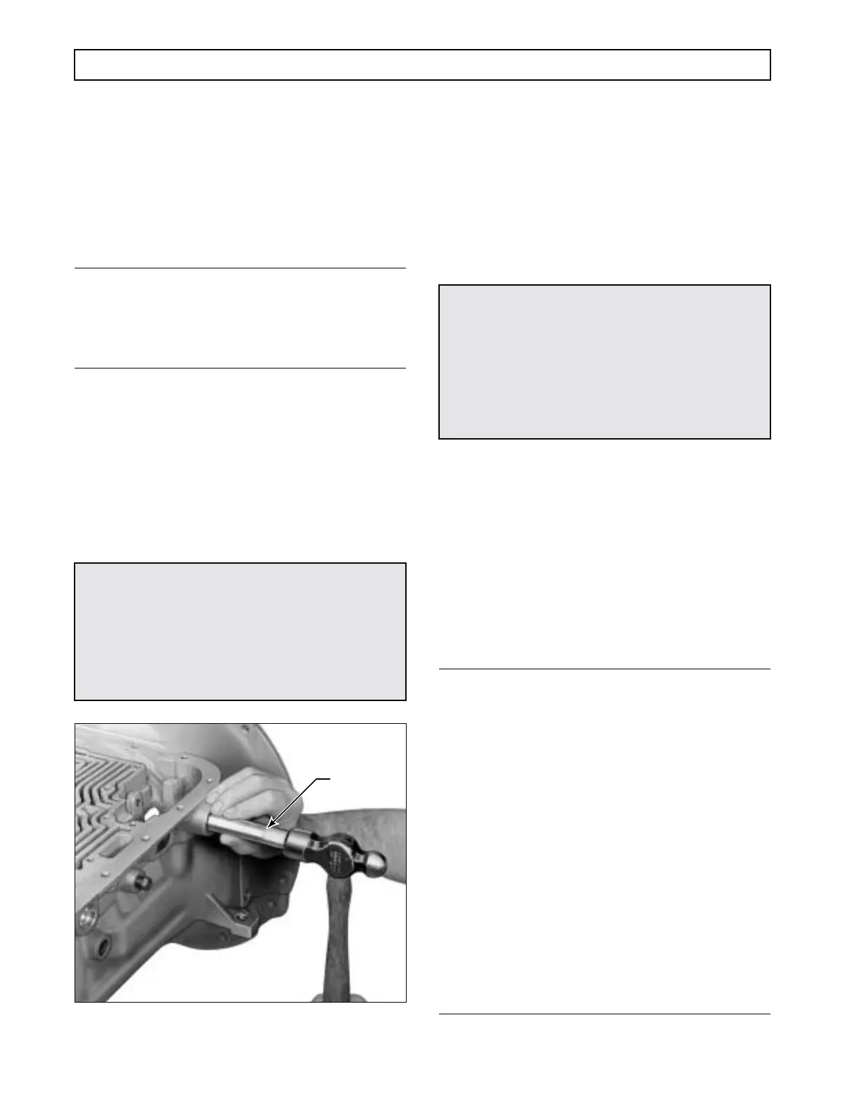
(2) Coat the ID of lip-type oil seal 61 (Fold-
out 12,B) with oil-soluble grease. Install the seal, lip
first, into the transmission case (Figure 6–58), using
special installer J 26282.
Figure 6–58. Installing Selector Shaft Oil Seal
(3) Hold selector lever 54 or 55 (Foldout
12,B) so the selector valve pin is facing the inside of
the case. Slide selector shaft 60 through the opening in
the transmission housing, oil seal, and into the slot in
selector lever 54 or 55. Attach locknut 59 and retainer
pin 57 (Figure 6–56). Tighten the locknut to 15–20 lb
ft (20–27 N·m).
(4) If removed, press new breather 7 (Fold-
out 12,A) into the housing.
(5) If governor support pin 12 was removed,
install a new pin using tool J 28684. If the tool is not
available, install the pin to dimensions shown in Fig-
ure 6–57.
(6) Install
1
⁄8 inch test plugs 8 and 13 (Fold-
out 12,A) into housing 11. Tighten the plugs to 48–60
lb in. (5.5–6.7 N·m).
6–16. PLANETARY CARRIER
ASSEMBLIES
NOTE:
• The disassembly and assembly procedures for all
the planetary carrier assemblies in the AT Series
transmissions differ only in the proper tool selec-
tion for the specific carrier assembly. Refer to
the tool chart and Figure 6–59 for specific use
and identity of the carrier (front, center, rear)
and tools involved. If the tool is common to all
the planetary carrier assemblies, its number will
be listed in the text. If the tool is not common,
the text will refer to the chart. For planetary car-
rier detailed information, refer to the exploded
views at the back of this manual.
• The hydraulic press, used with J 25587-01 Plan-
etary Rebuilding Set, must have a five-ton (45
kN) capacity, an adjustable press bed of 25 inch
(635 mm) minimum opening, and a pressure
gauge to assist in determining proper installa-
tion and staking of the pinion pins.
CAUTION:
Manual selector shafts that are center drilled at
their outer ends require an M10 x 1.5-6G nut
(metric thread). Shafts that are undrilled require
a
3
⁄8-16 nut (standard inch series). Use of the
wrong nut will damage both the shaft and nut.
Torque for either nut is 15–20 lb ft (20–27 N·m).
H02965
J 26282
CAUTION:
The alignment of the governor pin with the gover-
nor bore in the transmission housing is critical.
The governor must rotate freely, without interfer-
ence with either the case bore or the pin. Any in-
terference will result in damage to the governor
body, the bore in the housing, and/or the governor
driven gear.
 Loading...


